Rainbow Electronics TS81102G0 User Manual
Page 27
27
TS81102G0
2105C–BDC–11/03
Thermal Resistance
from Junction to
Ambient: RTHJA
A pin-fin type heat sink of a size 40 mm x 40 mm x 8 mm can be used to reduce thermal resis-
tance. This heat sink should not be glued to the top of the package as Atmel cannot guarantee
the attachment to the board in such a configuration. The heat sink could be clipped or screwed
on the board.
With such a heat sink, the Rthj-a is about 6
°
C/W (if we take 10
°
C/W for Rth from the junction
to air through the package and heat sink in parallel with 15
°
C/W from the junction to the board
through the package body, through balls and through board copper).
Without the heat sink, the Rth junction to air for a package reported on-board can be estimated
at 13 to 20
°
C/W (depending on the board used).
The worst value 20
°
C/W is given for a 1-layer board (13
°
C for a 4-layer board).
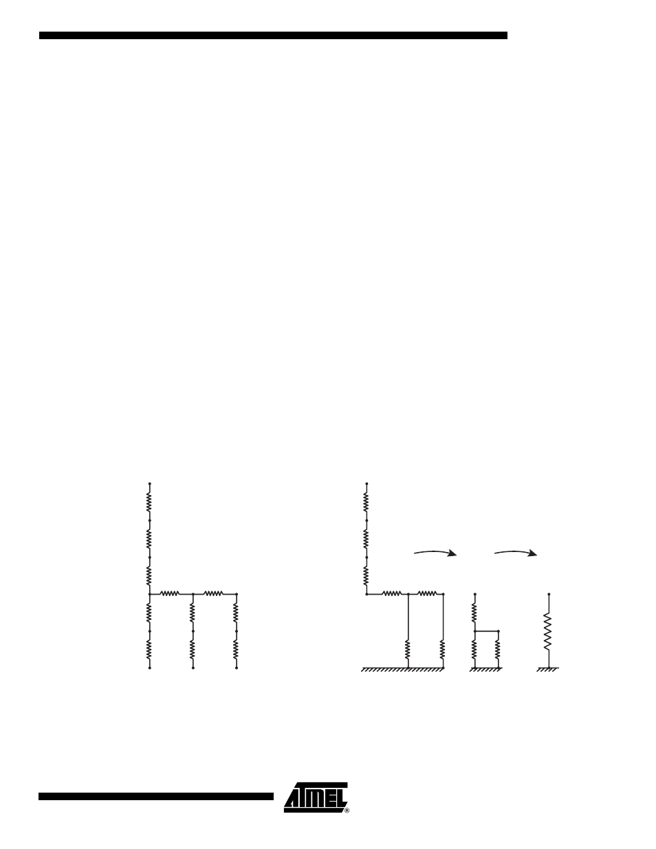
Thermal Resistance
from Junction to
Bottom of Balls
The thermal resistance from the junction to the bottom of the balls of the package corresponds
to the total thermal resistance to be considered from the silicon’s die junction to the interface
with a board. This thermal resistance is estimated to be 4.8
°
C/W max.
The following diagram points out how the previous thermal resistances were calculated for this
packaged device.
Figure 22.
Thermal Resistance from Junction to Bottom of Balls
Reduction
Infinite heatsink
at bottom of balls
Infinite heatsink
at bottom of balls
Infinite heatsink
at bottom of balls
Thermal Resistance Junction to bottom of balls = 4.8
°
C/W Max
Reduction
Silicon
Junction
Silicon Junction
Silicon Junction
Silicon Die
49 mm²
Assumptions:
Square die 7.0 x 7.0 = 49 mm², 75
µ
m thick Epoxy/Ag glue, 0.40 mm copper thickness under die,
Sn60Pb40 columns diameter 0.76 mm, 23 x 23 mm TBGA
Epoxy/Ag glue
Copper base
(Top half of thickness)
Copper base
Black ink
Top of
package
Thermal Resistance Junction to case typical =
0.10 + 0.60 + 0.05 + 0.05 + 0.25 = 1.05
°
C/W
Case were all Bottom of Balls are connected to infinite heatsink
(values are in
°
C/Watt)
Typical values
(values are in
°
C/Watt)
Thermal Resistance Junction to case Max = 1.40
°
C/W
2 internal
rows
(104 balls)
2 external
rows
(136 balls)
0.10
0.05
2.47
2.45
3.55
0.25
1.70
0.25
1.70
2.47
1.74
1.99
0.60
0.10
0.05
0.60
0.40
1.87
0.25
0.05
0.31
1.43
Silicon
Junction
λ
= 0.95Watt/
°
C
λ
= 0.025Watt/
°
C
Tape + glue
over balls
λ
= 0.02Watt/
°
C
Balls
PbSn
λ
= 0.40Watt/
°
C
λ
= 25Watt/
°
C
DEMUX
−
Axpproximative Model for 240 TBGA