Package description, Pin description – Rainbow Electronics TS81102G0 User Manual
Page 23
23
TS81102G0
2105C–BDC–11/03
Package Description
Pin Description
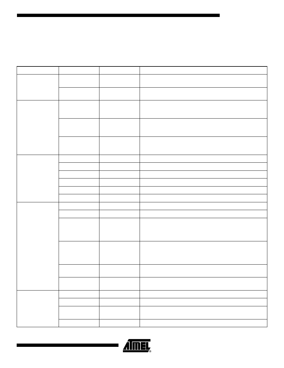
Table 7.
TS81102G0 Pin Description
Type
Name
Levels
Comments
Digital Inputs
I[0…9]
Differential ECL
Data input.
On-chip 100
Ω
differential termination resistor.
Clkln
Differential ECL
Clock input (Data Ready ADC).
On-chip 100
Ω
differential termination resistor.
Outputs
A[0…9]
→
H[0…9]
Adjustable Logic
Single
Data ready for port A to H.
Common mode is adjusted with VplusDOut. Swing is adjusted with
SwiAdj. 50
Ω
termination possible.
DR
Adjustable Logic
Differential
Data ready for channel A to H.
Common mode is adjusted with VplusDOut. Swing is adjusted with
SwiAdj. 50
Ω
termination possible.
RefA
→
RefH
Adjustable Single
Reference voltage for output channels A to H.
Common mode is adjustable with VplusDOut. 50
Ω
termination
possible.
Control Signals
ClklnType
TTL
DataReady or Dataready/2: logic 1: Data Ready.
RatioSel
TTL
DMUX ratio; logic 1: 1:4
Bist
TTL
Reset and Switch of built-in Self Test (BIST): logic 0: BIST active.
SwiAdj
0V ± 0.5V
Swing fine adjustment of output buffers.
Diode
Analog
Diode for chip temperature measurement.
NbBit
TTL
Number of bit 8 or 10: logic 1: 10-bit.
Synchronization
AsyncReset
TTL
Asynchronous reset: logic 1: reset on.
SyncReset
Differential ECL
Synchronous reset: active on rising edge.
DMUXDelAdjCtrl
Differential analog
input of ±0.5V
around 0V
common mode
Control of the delay line of DataReady input:
differential input = -0.5V: delay = 250 ps
differential input = 0V: delay = 500 ps
differential input = 0.5V: delay = 750 ps
ADCDelAdjCtrl
Differential analog
input of ±0.5V
around 0V
common mode
Control of the delay line for ADC:
differential input = - 0.5V: delay = 250 ps
differential input = 0V: delay = 500 ps
differential input = 0.5V: delay = 750 ps
ADCDelAdjln
Differential ECL
Stand-alone delay adjust input for ADC.
Differential termination of 100
Ω
inside the buffer.
ADCDelAdjOut
50
Ω
differential
output
Stand-alone delay adjust output for ADC.
Power Supplies
GND
Ground 0V
Common ground.
V
EE
Power -5V
Digital negative power supply.
V
PlusDOut
Adjustable power
from 0V to +3.3V
Common mode adjustment of output buffers.
V
CC
Power +5V
Digital positive power supply.