Rainbow Electronics TS81102G0 User Manual
Page 36
36
TS81102G0
2105C–BDC–11/03
Operation in DR/2
Mode
In DR/2 mode, the DMUX input clock can run at up to 1 GHz in 1:8 ratio or 500 MHz in 1:4
ratio, since the DR/2 clock from the ADC is half the sampling frequency.
Both cases are described in the following timing diagrams.
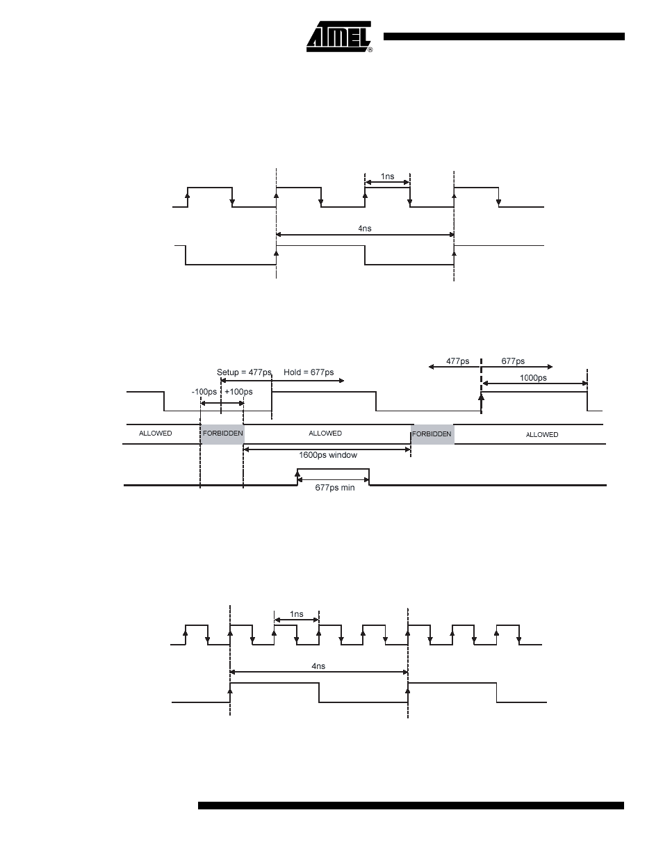
Figure 30. Synchronous Reset Operation in DR/2 Mode, 1:4 ratio, 500MHz (Full Speed) – Principle of Operation
Figure 31.
Synchronous Reset Operation in DR/2 Mode, 1:4 ratio, 500 MHz (Full-speed) – Timings
Note:
The clock edge to which the reset applies is the one identified by the arrow.
If the reset rising edge had occurred in the first allowed window (on the left), the reset would have been effective on the first
represented clock rising edge (first clock rising edge of the schematic, on the left of the edge represented with the arrow).
Figure 32.
Synchronous Reset Operation in DR/2 Mode, 1:8 ratio, 1GHz (Full Speed) – Principle of Operation
Fs/2
Sync_RESET
Fs/2
Times Zones
Allowed for the
reset
Sync_RESET
Fs/2
Sync_RESET