Adc to dmux connections – Rainbow Electronics TS81102G0 User Manual
Page 31
31
TS81102G0
2105C–BDC–11/03
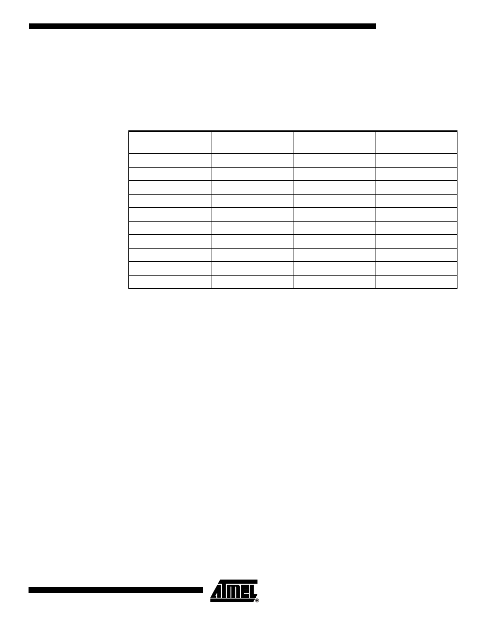
ADC to DMUX
Connections
The DMUX inputs configuration has been optimized to be connected to the TS8388B ADC.
The die in the TBGA package is up. For the ADC, different types of packages can be used
such as CBGA with die up or the CQFP68 down. The DMUX device being completely sym-
metrical, both ADC packages can be connected to the TBGA package of the DMUX criss-
crossing the lines (see Table 8).
Note:
The connection between the ADC evaluation board and the DMUX evaluation board requires a
4-pin shift to make the D0 pin match either the I7 or I0 pin of the DMUX evaluation board.
Table 8.
ADC to DMUX Connections
ADC Digital Outputs
CQFP68 Package
DMUX Data Inputs
TBGA Package
ADC Digital Outputs
CBGA Package
DMUX Data Inputs
TBGA Package
D0 I7
D0
I0
D1 I6
D1
I1
D2 I5
D2
I2
D3 I4
D3
I3
D4 I3
D4
I4
D5 I2
D5
I5
D6 I1
D6
I6
D7 I0
D7
I7
–
18 not connected
–
18 not connected
–
19 not connected
–
19 not connected