Rainbow Electronics TS81102G0 User Manual
Page 35
35
TS81102G0
2105C–BDC–11/03
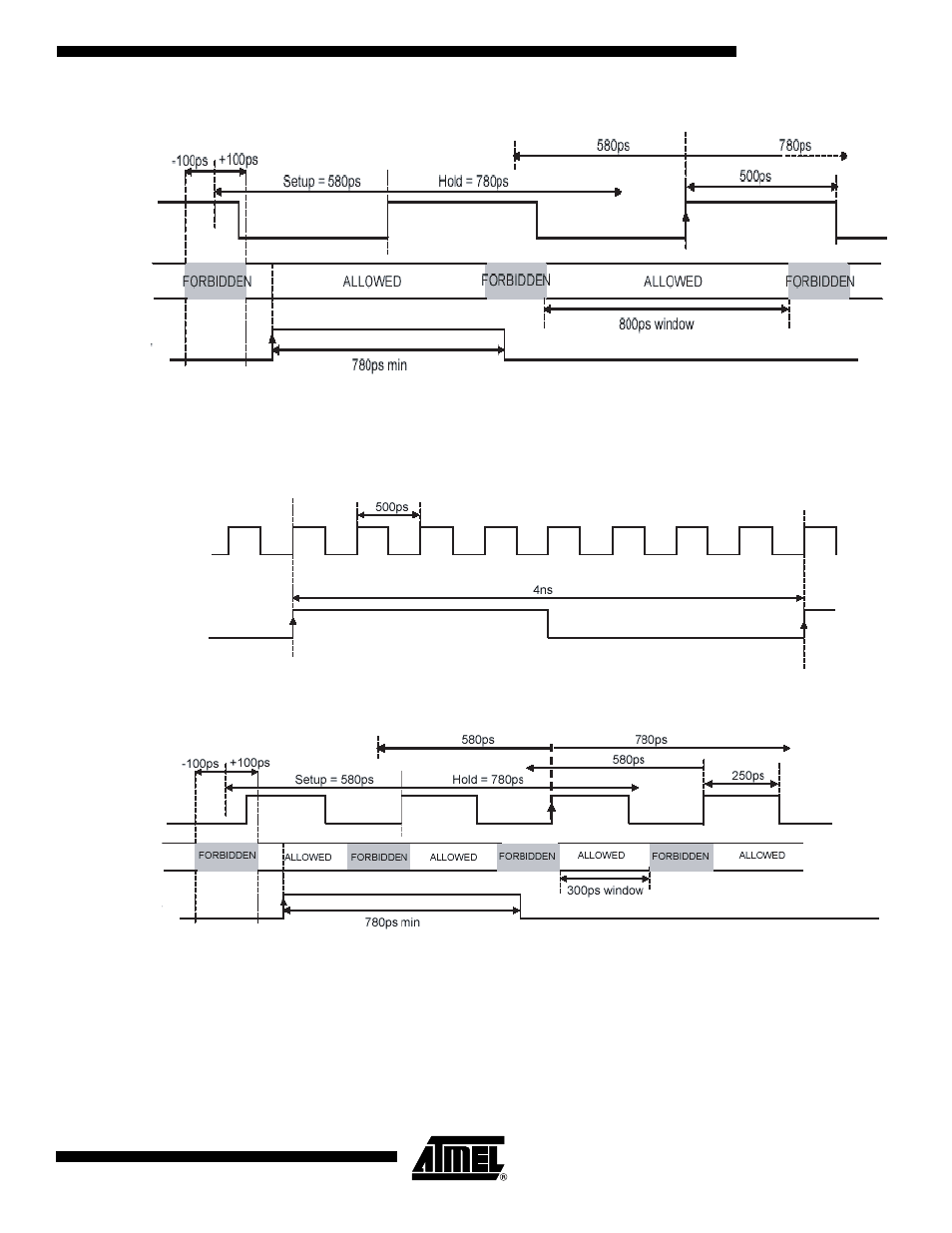
Figure 27. Synchronous Reset Operation in DR Mode, 1:4 ratio, 1GHz (Full Speed) – TIMINGS
Note:
The clock edge to which the reset applies is the one identified by the arrow.
If the reset rising edge had occurred in the second allowed window, the reset would have been effective on the third clock rising edge (not
represented, on the right of the edge represented with the arrow).
Figure 28. Synchronous Reset Operation in DR Mode, 1:8 ratio, 2 GHz (Full-speed) – Principle of Operation
Figure 29.
Synchronous Reset Operation in DR Mode, 1:8 ratio, 2 GHz (Full-speed) – Timings
Note:
The clock edge to which the reset applies is the one identified by the arrow.
If the reset rising edge had occurred in the second allowed window, the reset would have been effective on the fourth clock
rising edge (last clock rising edge, on the right of the edge represented with the arrow).
This case is the most critical one with only a 300 ps window for the reset.
Fs
Time Zones
Allowed for
the reset
Sync_RESET
Fs
Sync_RESET
Fs
Times Zones
Allowed for
the reset
Sync_RESET