Internal timing diagram – Rainbow Electronics TS81102G0 User Manual
Page 3
3
TS81102G0
2105C–BDC–11/03
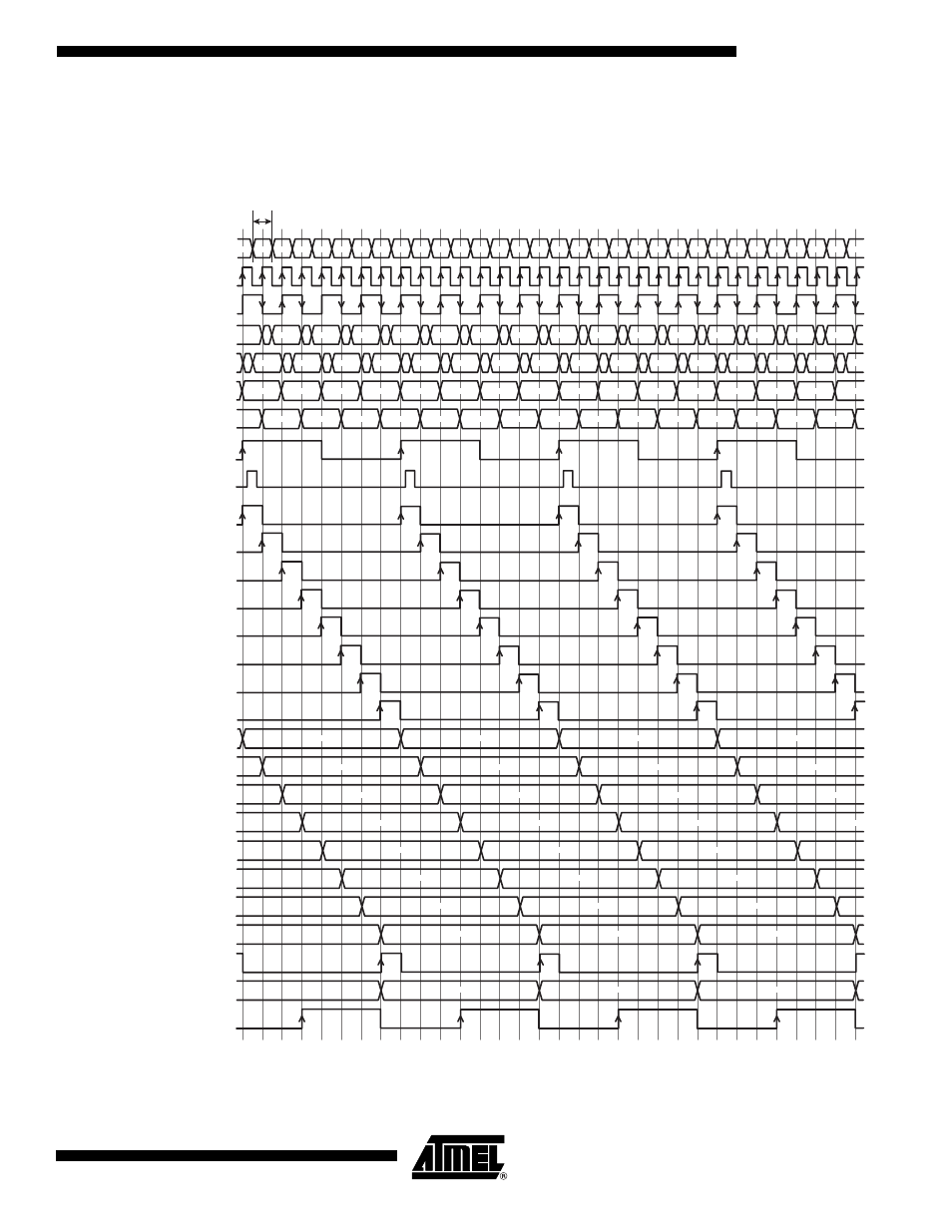
Internal Timing
Diagram
This diagram corresponds to an established operation of the DMUX with Synchronous Reset.
Figure 2.
Internal Timing Diagram
Data In
DR In = Fs
DR/2 In = Fs/2 = ClkPar
Master Even Latch
Master Odd Latch
Slave Even Latch
Slave Odd Latch
Synchronous reset = Fs/8
Internal reset pulse
Port Select A
Port Select B
Port Select C
Port Select D
Port Select E
Port Select F
Port Select G
Port Select H
Latch Select A
Latch Select B
Latch Select C
Latch Select D
Latch Select E
Latch Select F
Latch Select G
Latch Select H
A to H Port Out
A to H LatchOut
DROut
500 ps min
N
N+2
N+3
N+4
N+5
N+6
N+7
N+8
N+9
N+10 N+11 N+12 N+13 N+14 N+15 N+16 N+17 N+18 N+19 N+20 N+21 N+22 N+23 N+24
N
N+8
N+16
N+24
N+1
N+9
N+17
N+25
N+2
N+10
N+18
N+26
N+3
N+11
N+19
N+27
N+4
N+12
N+20
N+5
N+13
N+21
N+6
N+14
N+22
N+7
N+15
N+23
N to N+7
N+8 to N+15
N+16 to N+23
N+25 N+26 N+27 N+28 N+29 N+30 N+31
N+24
N+26
N+28
N+30
N+14
N+16
N+18
N+20
N+22
N+6
N+8
N+10
N+12
N
N+2
N+4
N+3
N+5
N+7
N+9
N+11
N+13
N+15
N+17
N+19
N+21
N+23
N+25
N+27
N+29
N+1
N+2
N+3
N+4
N+5
N+6
N+7
N+8
N+9
N+10
N+11
N+12
N+13
N+14
N+15
N+16
N+17
N+18
N+19
N+20
N+21
N+22
N+23
N+24
N+25
N+26
N+27
N+28
N+29
N
N+1
N+31
N+30
N+1