Table 1. slave address select – Rainbow Electronics MAX11008 User Manual
Page 21
Slave Address
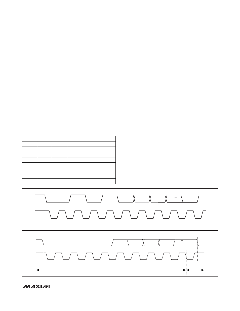
A bus master initiates communication with a slave
device by issuing a START condition followed by the 7-
bit slave address and a read/
write (R/W) bit (see Figure
7). When the device recognizes its slave address, it is
ready to accept or send data depending on the R/
W
bit. When the MAX11008 recognizes its slave address,
it issues an ACK by pulling SDA low for one clock cycle
and is ready to accept or send data depending on the
R/
W bit that was sent.
The MAX11008 has eight user-selectable slave address-
es, which are set through inputs A0, A1, and A2 (see
Table 1). This feature allows up to eight MAX11008
devices to share the same bus inputs. The 4 MSBs D[7:4]
are factory set, and the 3 LSBs are user-selectable.
Bus Timing
At power-up, the bus timing is set for I
2
C fast-mode
(F/S mode), which allows I
2
C clock rates up to 400kHz.
The MAX11008 can also operate in high-speed mode
(HS mode) to achieve I
2
C clock rates up to 3.4MHz.
See Figure 4 for I
2
C bus timing.
HS I
2
C Mode
Select HS mode by addressing all devices on the bus
with the HS-mode master code 0000 1XXX (X = don’t
care). After successfully receiving the HS-mode master
code, the MAX11008 issues a NACK, allowing SDA to
be pulled high for one clock cycle (see Figure 8). After
the NACK, the MAX11008 operates in HS mode. The
master must then send a repeated START (Sr) followed
by a slave address to initiate HS-mode communication.
If the master generates a STOP condition, the
MAX11008
Dual RF LDMOS Bias Controller with
Nonvolatile Memory
______________________________________________________________________________________
21
SDA
SCL
0
0
A2
A1
A0
R/W
A
1
2
3
4
5
6
7
8
9
S
1
1
Figure 7. Slave Address Bits
SDA
1
2
3
4
0
0
0
0
5
6
7
8
1
X
X
X
9
A
Sr
HS MODE
F/S MODE
Figure 8. F/S-Mode to HS-Mode Transfer
A2
A1
A0
ADDRESS
0
0
0
0101000
0
0
1
0101001
0
1
0
0101010
0
1
1
0101011
1
0
0
0101100
1
0
1
0101101
1
1
0
0101110
1
1
1
0101111
Table 1. Slave Address Select