Rf01, Data filtering and clock recovery, Data validity blocks rssi – Rainbow Electronics RF01 User Manual
Page 4
RF01
Data Filtering and Clock Recovery
The output data filtering can be completed by an external capacitor or by using digital filtering
according to the final application.
Analog operation:
The filter is an RC type low-pass filter and a Schmitt-trigger (St). The resistor (10k) and the St is
integrated on the chip. An (external) capacitor can be chosen according to the actual bit-rate. In this
mode the receiver can handle up to 256 kbps data rate.
Digital operation:
The data filter is a digital realization of an analog RC filter followed by a comparator with hysteresis.
In this mode there is a clock recovery circuit (CR), which can provide synchronized clock to the data. With
this clock the received data can fill the RX Data FIFO. The CR has three operation modes: fast, slow, and
automatic. In slow mode, its noise immunity is very high, but it has slower settling time and requires more
accurate data timing than in fast mode. In automatic mode the CR automatically changes between fast
and slow modes. The CR starts in fast mode, then automatically switches to slow mode after locking.
(Only the data filter and the clock recovery use the bit-rate clock. Therefore, in analog mode, there is
no need for setting the correct bit-rate.)
Data Validity Blocks
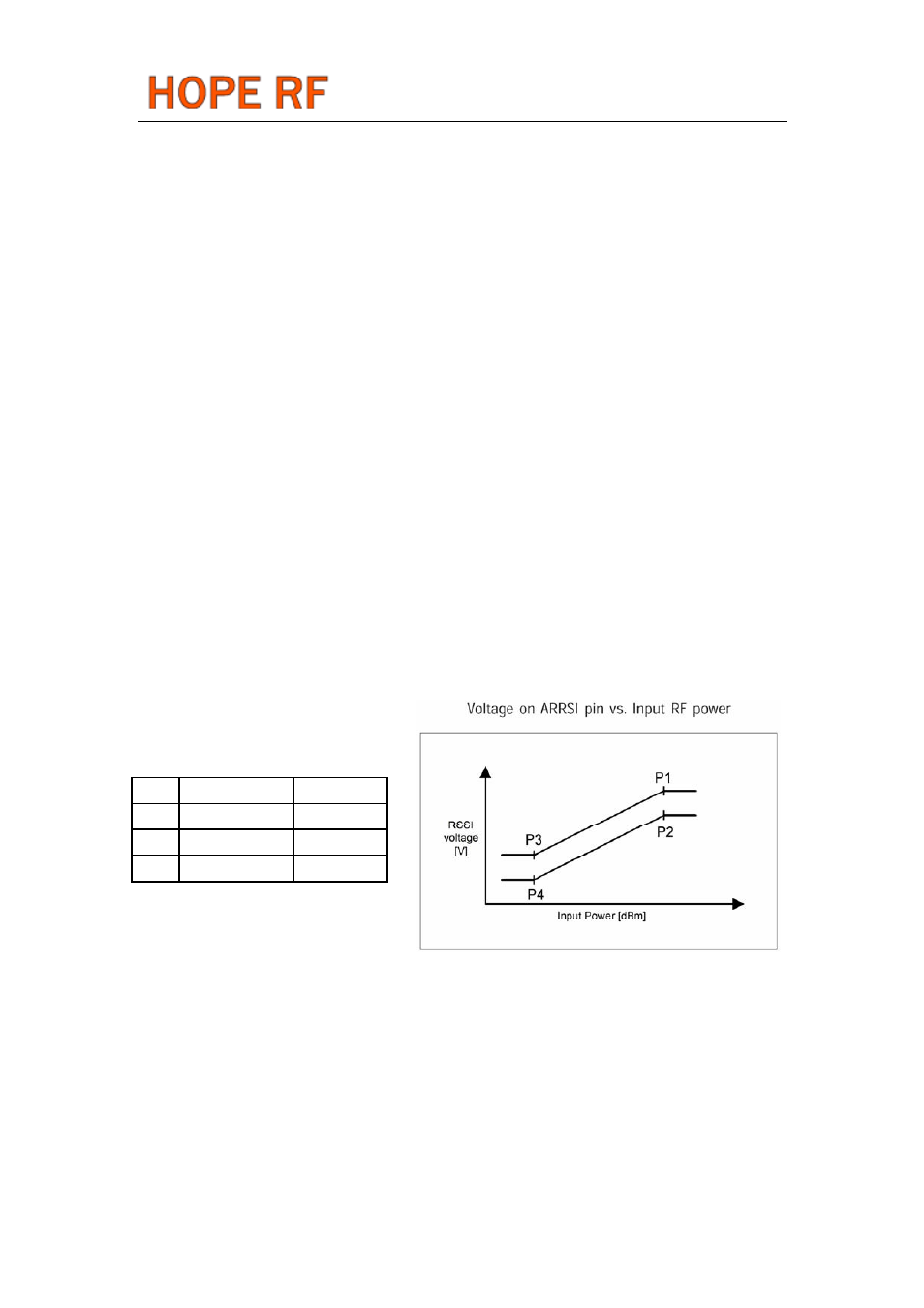
RSSI
A digital RSSI output is provided to monitor the input signal level. It goes high if the received signal
strength exceeds a given preprogrammed level. An analog RSSI signal is also available. The RSSI
settling time depends on the filter capacitor used.
P1
-65 dBm
1300 mV
P2
-65 dBm
1000 mV
P3
-100 dBm
600 mV
P4
-100 dBm
300 mV
DQD
The Data Quality Detector monitors the I/Q output of the baseband amplifier chain by counting the
consecutive correct 0->1, 1->0 transitions. The DQD output indicates the quality of the signal to be
demodulated. Using this method it is possible to "forecast" the probability of BER degradation. The
programmable DQD parameter defines the threshold for signaling the good/bad data quality by the digital
one-bit DQD output. In cases when the deviation is close to the bit rate, there should be four transitions
during a single one bit period in the I/Q signals. As the bit rate decreases in comparison to the deviation,
more and more transitions will happen during a bit period.
Tel: +86-755-86096587 Fax: +86-755-86096602 E-mail: [email protected] http://www.hoperf.com