Rf01 – Rainbow Electronics RF01 User Manual
Page 15
RF01
Tel: +86-755-86096587 Fax: +86-755-86096602 E-mail: [email protected] http://www.hoperf.com
In both cases (2a and 2b) when the VDI indicates poor receiving conditions (VDI goes low) the
output register is automatically cleared. It’s suggested to use when one receiver receives signal from
more than one transmitter.
3
, (a1=1, a0=1) It is similar to the 2a and 2b modes, but 3 is suggested to use when a receiver
operates with only one transmitter. After a complete measuring cycle, the measured value is held
independently of the sate of VDI signal.
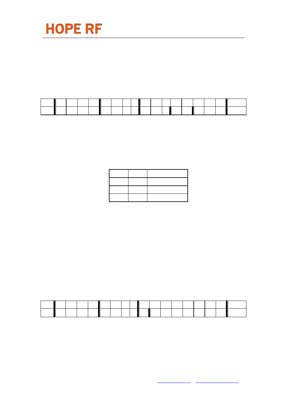
Data Filter Command
bit 15 14 13
12 11 10
9
8
7
6
5
4
3
2
1
0
POR
1
1
0
0
0
1
0
0
al
ml
1
s1
s0
f2
f1 f0 C42Ch
Bit 7
Clock recovery (CR) auto lock control if set. It means that the CR start in fast mode
after locking it automatically switches to slow mode.
Bit 6
Clock recovery lock control 1: fast mode, fast attack and fast release 0: slow mode,
slow attack and slow release Using the slower one requires more accurate bit
timing (see Data Rate Command).
Bit3-4
Select the type of the data filter:
s1
s0
Filter Type
0
0
Reserved
0
1
Digital
1
0
Reserved
Digital: this is a digital realization of an analog RC filter followed by a comparator with hysteresis.
The time constant is automatically adjusted to the bit rate defined by the Data Rate Command.
Analog RC filter: the demodulator output is fed to the pin 7 over a 10 kOhm resistor. The filter
characteristic is set by the external capacitor connected to this pin and VSS. (Suggested value for 9600
bps is 3.3 nF)
Bit 0-2
Note:
To let the DQD report "good signal quality" the threshold parameter should be less than 4 in the
case when the bit-rate is close to the deviation. At higher deviation/bit-rate settings higher threshold
parameter can report "good signal quality" as well.
Data Rate Command
bit 15 14 13
12 11 10 9
8
7
6
5
4
3
2
1
0
POR
1
1
0
0
1
0
0
0
cs
r6
r5
r4
r3
r2
r1 r0 C823h
The expected bit rate of the received data stream is determined by the 7-bit value R (bits r6 to r0)
and the 1 bit cs.
BR = 10 MHz / 29 / (R+1) / (1 + cs*7)
In the receiver set R according the next function:
R= (10 MHz / 29 /(1 + cs*7)/ BR) – 1
Apart from setting custom values, the standard bit rates from 600 bps to 115.2 kbps can be
approximated with small error.