Rf01 – Rainbow Electronics RF01 User Manual
Page 13
RF01
Tel: +86-755-86096587 Fax: +86-755-86096602 E-mail: [email protected] http://www.hoperf.com
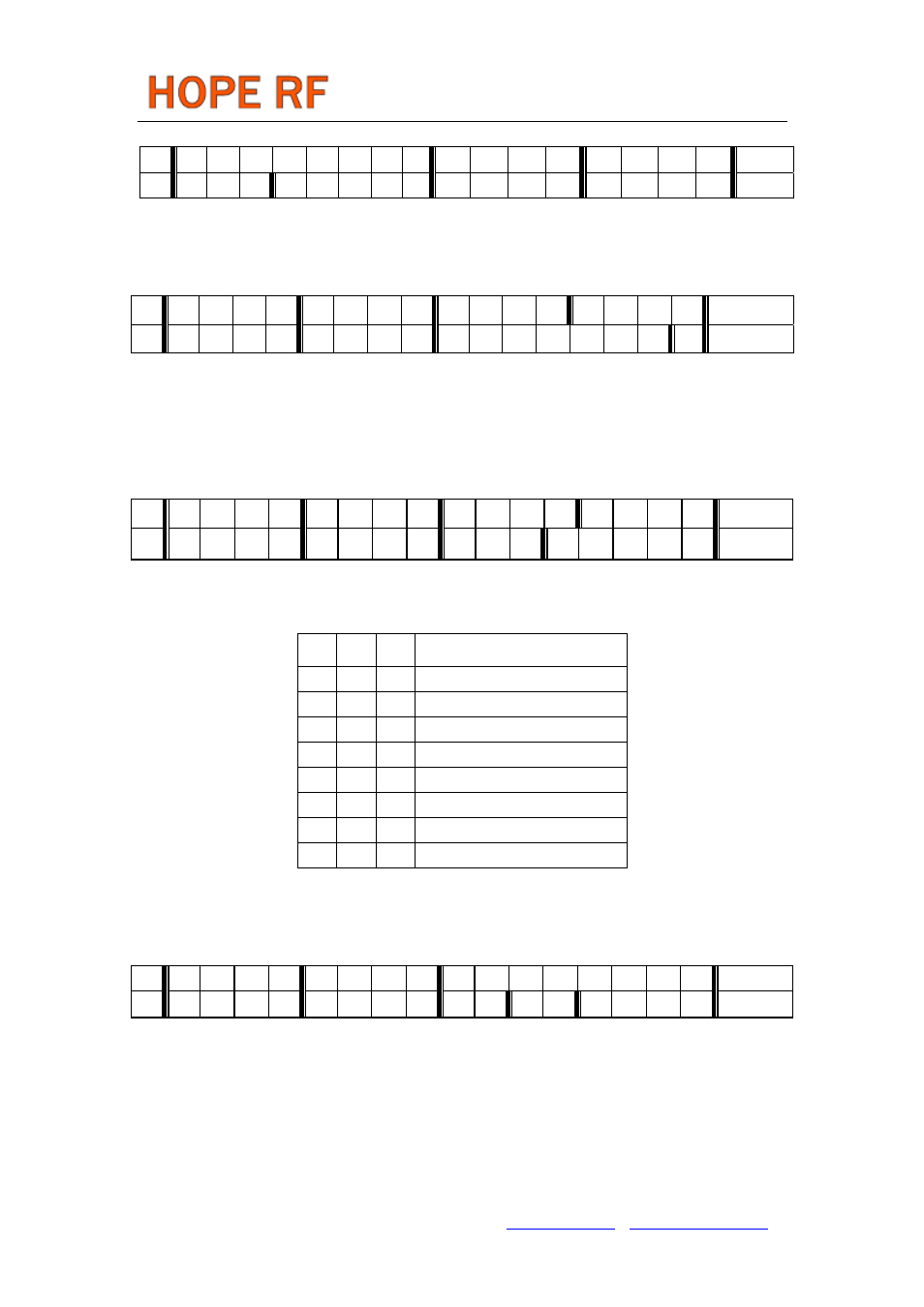
Wake-Up Timer Command
bit
15
14
13
12
11
10
9
8
7 6 5 4 3 2 1 0 POR
1 1 1 r4 r3 r2 r1
r0
m7
m6
m5
m4
m3
m2
m1 m0 E196h
The wake-up time period can be calculated by M
T
wake-up
= M * 2
R
ms
Low Duty-Cycle Command
bit 15
14 13 12
11 10 9 8 7 6 5 4 3 2 1 0 POR
1 1 0 0 1 1 0 0 d6
d5
d4
d3
d2
d1
d0 en CCOEh
With this command Low Duty-Cycle operation can be set in order to decrease the average power
consumption. The time cycle is determined by the Wake-Up Timer Command.
The Duty-Cycle is calculated by D
D.C.= (D * 2 +1) / M *100%
Low Battery Detector and Microcontroller Clock Divider Command
bit 15 14 13 12 11 10 9 8 7 6 5 4 3 2 1 0 POR
1 1 0 0 0 0 1 0 d2
d1
d0
t4
t3
t2
t1 t0 C200h
The 5-bit value T of t4-t0 determines the threshold voltage of the threshold voltage V
lb
of the detector:
V
lb
= 2.2 V + T * 0.1 V
Clock divider configuration:
d2 d1 d0
Clock Output Frequency [MHz]
0
0
0
1
0
0
1
1.25
0
1
0
1.66
0
1
1
2
1
0
0
2.5
1
0
1
3.33
1
1
0
5
1
1
1
10
AFC Command
bit 15 14 13 12 11 10 9 8 7 6 5 4 3 2 1 0 POR
1 1 0 0 0 1 1 0 a1
a0
rl1
rl0
st fi oe en C6F7h
Bit 0 (en) enables the calculation of the offset frequency by the AFC circuit (it allows the addition of the
content of the output register to the frequency control word of the PLL).
Bit 1 (oe) when set, enables the output (frequency offset) register Bit 2 (fi) when set, switches the circuit to
high accuracy (fine) mode. In this case the processing time is about four times longer, but the measurement
uncertainty is less than half.
Bit 3 (st) strobe edge, when st goes to high, the actual latest calculated frequency error is stored into the
output registers of the AFC block.