Rf01 – Rainbow Electronics RF01 User Manual
Page 12
RF01
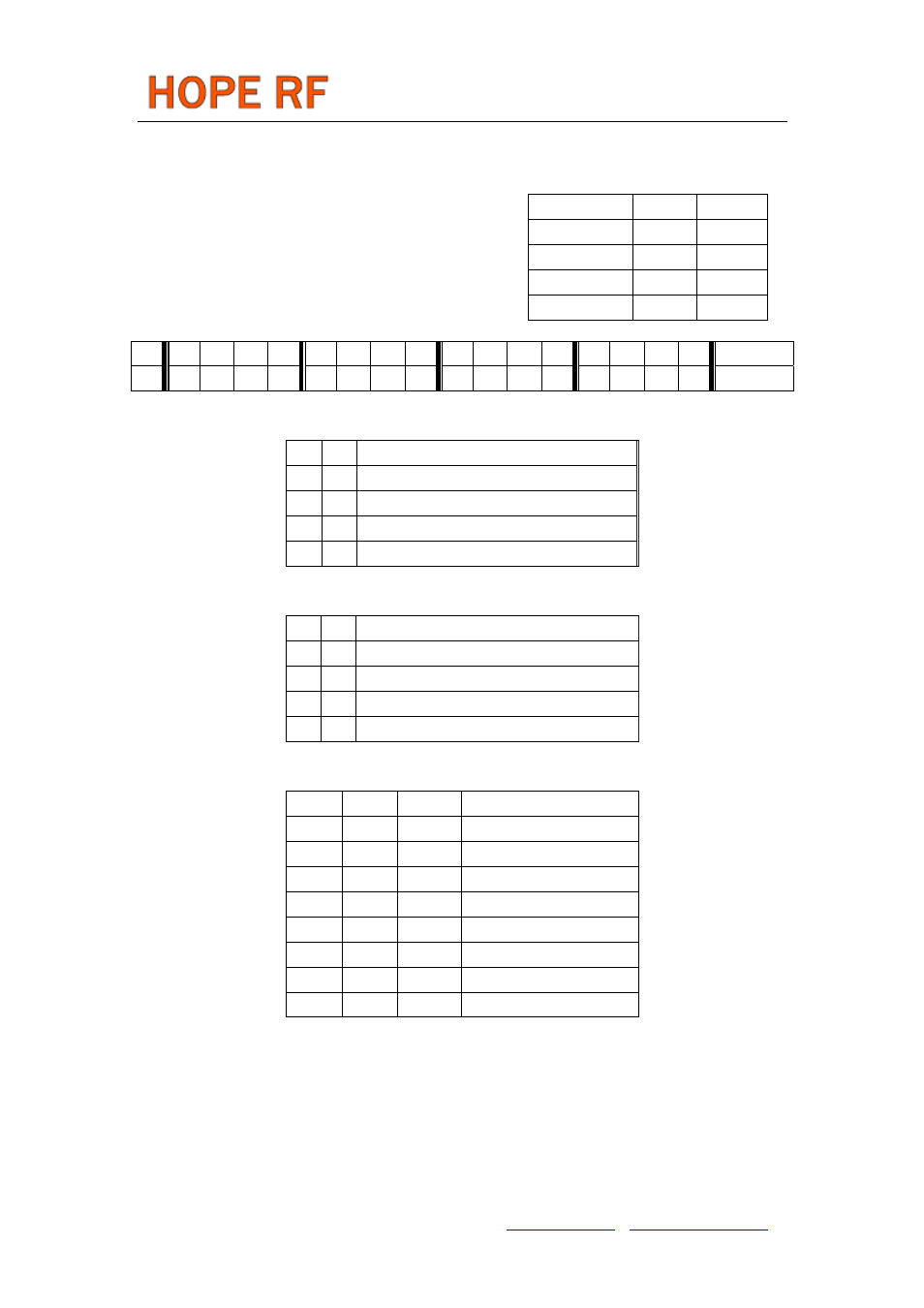
The constants C1 and C2 are determined
by the selected band as:
Band [MHz]
C1
C2
315
1
31
433
1
43
868
2
43
915
3
30
The 12-bit Frequency Setting Command
value F. The value F should be in the range of 96 and 3903.
When F is out of range, the previous value is kept. The
synthesizer center frequency f can be calculated as:
f
0
= 10 MHz * C1 * (C2 + F/4000)
Receiver Setting Command
bit 15 14 13
12 11 10
9 8 7 6 5 4 3 2 1 0 POR
1 1 0 0 0 0 0 0 d1
d0
g1
g0
r2
r1
r0 en C0C1h
Bits 7-6 select the VDI (valid data indicator) signal:
d1 d0 VDI output
0
0
Digital RSSI Out (DRSSI)
0
1
Data Quality Detector Output (DQD)
1
0 Clock recovery lock
1 1 Always
Bits 5-4 LNA gain set:
g1 g0 GLNA (dB relative to max. G)
0 0 0
0 1 -14
1 0 -6
1 1 -20
Bits 3-1 control the threshold of the RSSI detector:
r2
r1
r0
RSSIsetth [dBm]
0
0
0
-103
0
0
1
-97
0
1
0
-91
0
1
1
-85
1
0
0
-79
1
0
1
-73
1
1
0
-67
1
0
1
-61
The RSSI threshold depends on the LNA gain, the real RSSI threshold can be calculated:
RSSI
th
= RSSI
setth
+ G
LNA
Bit 0 (en) enables the whole receiver chain and crystal oscillator when set. Enable/disable of the wake-up
timer and the low battery detector are not affected by this setting.
Note:
Clock tail is not generated when the crystal oscillator is controlled by en bit.
Tel: +86-755-86096587 Fax: +86-755-86096602 E-mail: [email protected] http://www.hoperf.com