Rf01, Crystal selection guidelines – Rainbow Electronics RF01 User Manual
Page 21
RF01
radio, switching noise may be present on the V
dd
line. Follow the manufacturer’s recommendations how to
decrease the ripple of the regulator IC and/or how to shift the switching frequency.
Related control commands
“Reset Mode Command”
Setting bit<0> to high will change the reset mode to normal from the default sensitive.
“SW Reset Command”
Issuing FF00h command will trigger software reset. See the Wake-up Timer Command.
CRYSTAL SELECTION GUIDELINES
The crystal oscillator of the RF01 requires a 10 MHz parallel mode crystal. The circuit contains an
integrated load capacitor in order to minimize the external component count. The internal load
capacitance value is programmable from 8.5 pF to 16 pF in 0.5 pF steps. With appropriate PCB layout,
the total load capacitance value can be 10 pF to 20 pF so a variety of crystal types can be used.
When the total load capacitance is not more than 20 pF and a worst case 7 pF shunt capacitance (C
0
)
value is expected for the crystal, the oscillator is able to start up with any crystal having less than 300
ohms ESR (equivalent series loss resistance). However, lower C
0
and ESR values guarantee faster
oscillator startup.
The crystal frequency is used as the reference of the PLL, which generates the local oscillator
frequency (f
LO
). Therefore f
LO
is directly proportional to the crystal frequency. The accuracy requirements
for production tolerance, temperature drift and aging can thus be determined from the maximum
allowable local oscillator frequency error.
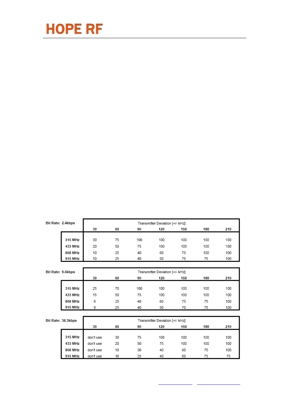
Maximum XTAL Tolerances Including Temperature and Aging [ppm]
Whenever a low frequency error is essential for the application, it is possible to “pull” the crystal to
Tel: +86-755-86096587 Fax: +86-755-86096602 E-mail: [email protected] http://www.hoperf.com