Rf01 – Rainbow Electronics RF01 User Manual
Page 16
RF01
Data rate accuracy requirements:
Clock recovery in slow mode: ∆BR/BR<1/(29*N
bit
)
Clock recovery in fast mode: ∆BR/BR<3/(29*N
bit
)
BR is the bit rate set in the receiver and ∆BR is bit rate difference between the transmitter and the
receiver. N is the maximal number of bit consecutive ones or zeros in the data stream. It is recommended
for long data packets to include enough 1/0 and 0/1 transitions, and be careful to use the same division
ratio in the receiver and in the transmitter.
∆BR is a theoretical limit for the clock recovery circuit. Clock recovery will not work above this limit.
The clock recovery circuit will always operate below this limit independently from process, temperature,
or V
dd
condition.
E.g. Supposing a maximum length of consecutive zeros or ones in the data stream is less than 5 bits,
the necessary relative accuracy is 0.68% in slow mode and 2.1% in fast mode.
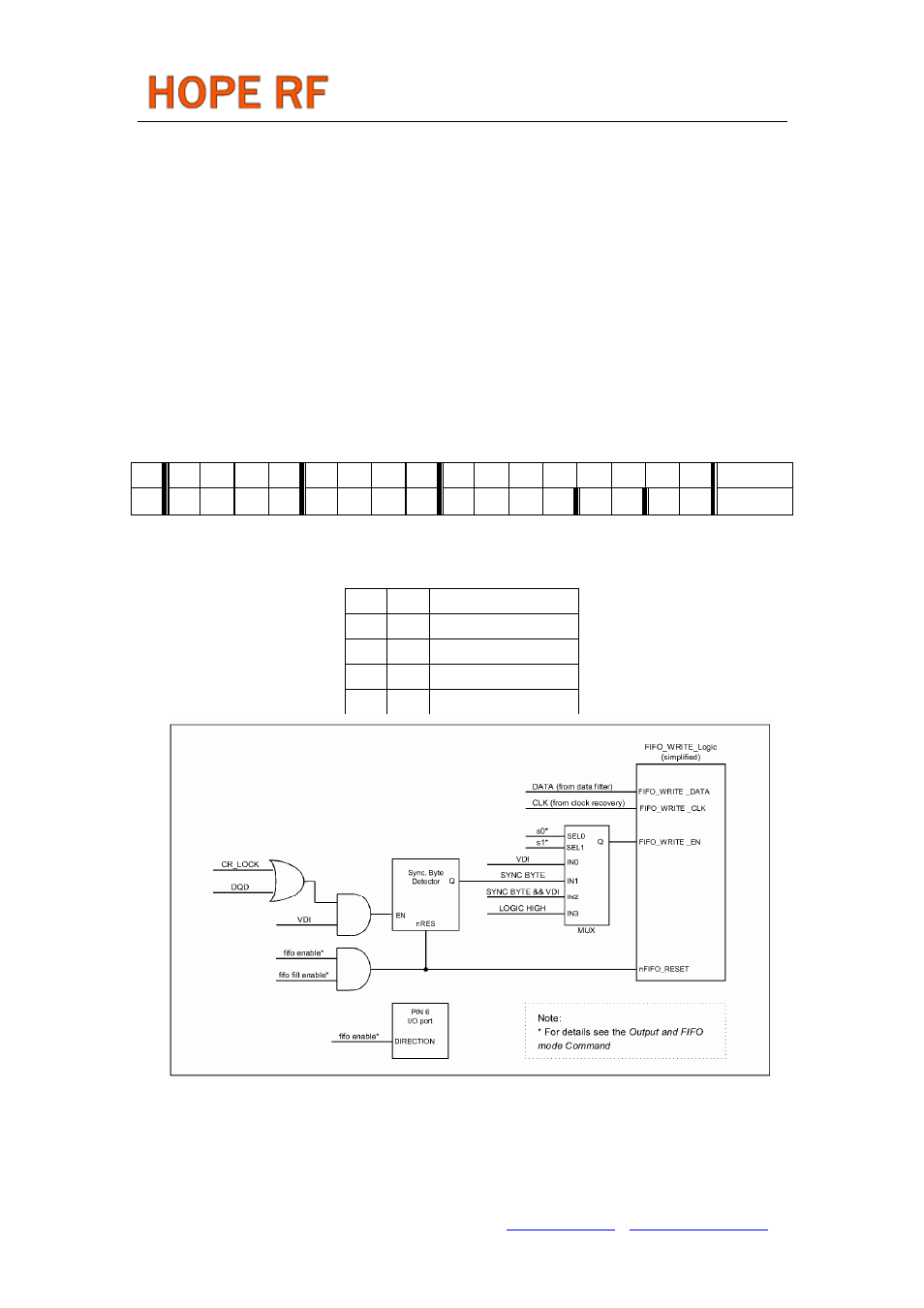
Output and FIFO Mode Command
bit 15 14 13 12 11 10 9 8 7 6 5 4 3 2 1 0 POR
1 1 0 0 1 1 1 0 f3
f2
f1
f0
s1
s0
ff fe CE85h
Bit 4-7
level.
Bit 2-3
s1 s0
0
0
VDI
0
1
Sync. Word
1 0 reserved
1
1
Always
Note:
VDI (Valid Data Indicator) see further details in Receiver Control Word.
Bit 1: <ff> Enables FIFO fill after synchron word reception. FIFO fill stops when this bit is cleared.
Bit 0: <fe> Enables the 16bit deep FIFO mode. To clear the FIFO’s counter and content, it has to be
set zero.
Note:
To restart the synchron word reception bit 1 should be cleared and set.This action will initialize the
Tel: +86-755-86096587 Fax: +86-755-86096602 E-mail: [email protected] http://www.hoperf.com