Table 30. status3 register format, Table 31b. power-good assertion delay – Rainbow Electronics MAX5961 User Manual
Page 30
MAX5961
0 to 16V, Quad, Hot-Swap Controller
with 10-Bit Current and Voltage Monitor
30
______________________________________________________________________________________
Power-Good Detection and PG_ Outputs
The PG_ output for a given channel is asserted when
the voltage at MON_ is between the undervoltage and
overvoltage critical limits. The status of the power-good
signals is maintained in register status3[3:0]. A value of
1 in any of the pg[] bits indicates a power-good condi-
tion, regardless of the POL setting, which only affects
the PG_ output polarity. The open-drain PG_ output can
be configured for active-high or active-low status indi-
cation by the state of the POL input (see Table 30).
The POL input sets the value of bit 5 of the status3 reg-
ister, which is a read-only bit; the state of the POL input
can be changed at any time during operation and the
polarity of the PG_ outputs will change accordingly.
The assertion of the PG_ output is delayed by a user-
selectable time delay of 50ms, 100ms, 200ms, or
400ms (see Tables 31a and 31b).
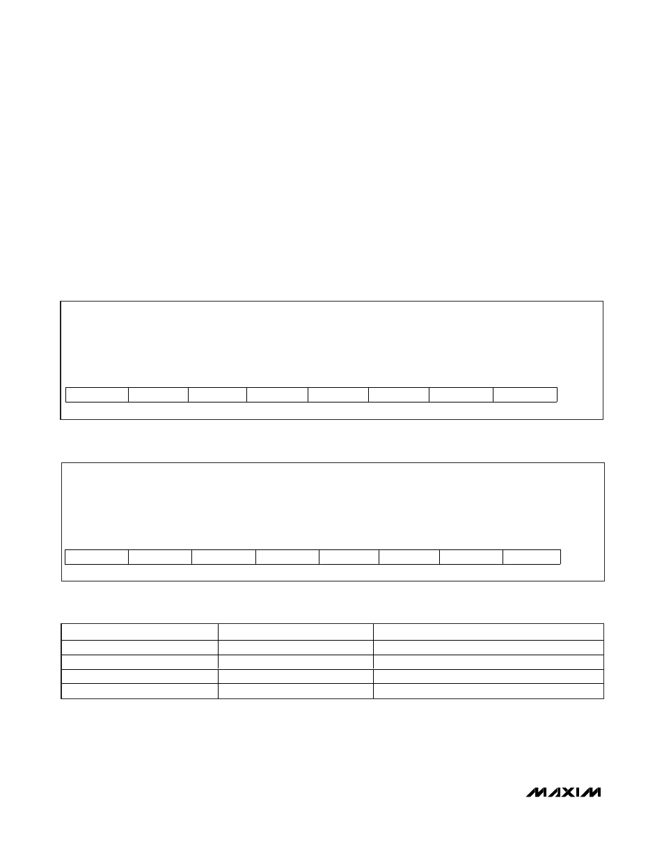
Table 30. status3 Register Format
Description:
Power-good status register; RETRY, POL, and alert bits
Register Title:
status3
Register Address:
0x62
R
R
R
R/W
R
R
R
R
RESET
VALUE
RETRY
POL
alert
pg[4]
pg[3]
pg[2]
pg[1]
—
bit 7
bit 6
bit 5
bit 4
bit 3
bit 2
bit 1
bit 0
Table 31a. Power-Good Assertion Delay-Time Register Format
Description:
Power-good assertion delay-time register
Register Title:
pgdly
Register Address:
0x66
R/W
R/W
R/W
R/W
R/W
R/W
R/W
R/W
RESET
VALUE
Ch4_dly1
Ch4_dly0
Ch3_dly1
Ch3_dly0
Ch2_dly1
Ch2_dly0
Ch1_dly1
Ch1_dly0
0x00
bit 7
bit 6
bit 5
bit 4
bit 3
bit 2
bit 1
bit 0
Table 31b. Power-Good Assertion Delay
Chx_dly1
Chx_dly0
PG_ ASSERTION DELAY (ms)
0
0
50
0
1
100
1
0
200
1
1
400