Table 4b. status1 register format – Rainbow Electronics MAX5961 User Manual
Page 18
MAX5961
0 to 16V, Quad, Hot-Swap Controller
with 10-Bit Current and Voltage Monitor
18
______________________________________________________________________________________
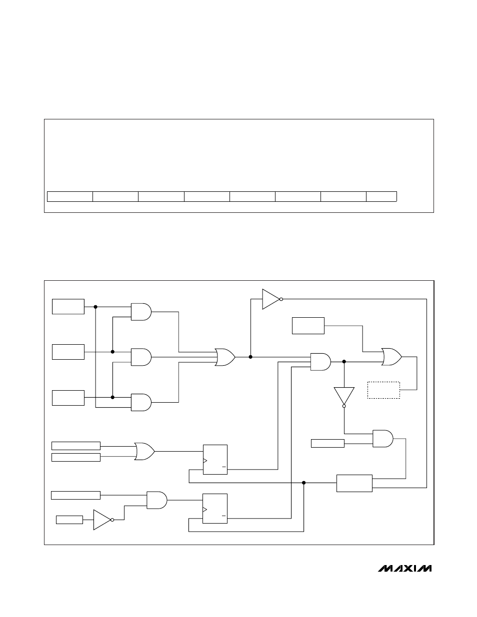
Figure 1 shows the detailed logic operation of the hot-
swap enable signals Chx_EN1, Chx_EN2, and ON_, as
well as the effect of various fault conditions.
An input undervoltage threshold control for enabling the
hot-swap channel can be implemented by placing a
resistive divider between the drain of the hot-swap FET
and ground, with the midpoint connected to ON_. The
turn-on threshold voltage for the channel is then:
V
EN
= 0.6V x (R1 + R2)/R2
The maximum rating for the ON_ pin is 6V; do not
exceed this value.
Table 4b. status1 Register Format
Description:
Channel grouping (three-state MODE input), fault-detection behavior (three-state PROT input), and
ON_ inputs status register
Register Title:
status1
Register Address:
0x60
R
R
R
R
R
R
R
R
RESET
VALUE
prot[1]
prot[0]
mode[1]
mode[0]
ON4
ON3
ON2
ON1
—
bit 7
bit 6
bit 5
bit 4
bit 3
bit 2
bit 1
bit 0
ON_
FORCE-ON
BIT
200ms DELAY,
THEN PULSE
CHANNEL
ENABLED
EN1_BIT
S
R
Q
Q
EN2_BIT
ANALOG SLOW_TRIP
RETRY PIN
ANALOG FAST_TRIP
UV/OV CRITICAL
PROT
S
R
Q
Q
Figure 1. Channel On-Off Control Logic Functional Schematic