Table 4a. status1 register function, Table 3. chxen register format – Rainbow Electronics MAX5961 User Manual
Page 17
MAX5961
0 to 16V, Quad, Hot-Swap Controller
with 10-Bit Current and Voltage Monitor
______________________________________________________________________________________
17
Hot-Swap Channels On-Off Control
Depending on the configuration of the Chx_EN1 and
Chx_EN2 bits, when V
IN
is above the V
UVLO
threshold
and the ON_ input reaches its internal threshold, the
MAX5961 turns on the external n-channel MOSFET for
the corresponding channel, allowing power to flow to
the load. The channel is enabled depending on the out-
put of a majority function. Chx_EN1, Chx_EN2, and ON_
are the inputs to the majority function and the channel is
enabled when two or more of these inputs are 1.
Channel enabled = (Chx_EN1 x Chx_EN2) +
(Chx_EN1 x ON_) + (Chx_EN2 x ON_)
The inputs ON_ and Chx_EN2 can be set externally; the
initial state of the Chx_EN2 bits in register chxen is set
by the state of the HWEN input when IN rises above
V
UVLO
. The ON_ inputs connect to internal precision
analog comparators with a 0.6V threshold. Whenever
V
ON_
is above 0.6V, the corresponding ON_ bit in reg-
ister status1[3:0] is set to 1. The inputs Chx_EN1 and
Chx_EN2 can be set using the I
2
C interface; the
Chx_EN1 bits have a default value of 0. This makes it
possible to enable or disable each of the MAX5961
channels independently with or without using the I
2
C
interface (see Tables 3, 4a, and 4b).
Table 4a. status1 Register Function
REGISTER
ADDRESS
BIT RANGE
DESCRIPTION
[3:0]
ON_ Inputs State
1 = ON_ above 600mV channel enable threshold
0 = ON_ below 600mV channel enable threshold
Bit 0: ON1
Bit 1: ON2
Bit 2: ON3
Bit 3: ON4
[5:4]
Channel Grouping Mode (MODE Input)
00 = Grouped (MODE unconnected)
01 = Paired (MODE high)
10 = Independent (MODE low)
11 = (Not possible)
0x60
[7:6]
Voltage Critical Behavior (PROT Input)
00 = Assert ALERT upon UV/OV critical (same as UV/OV warning behavior)
01 = Assert ALERT and deassert PG_ upon UV/OV critical
10 = Assert ALERT, deassert PG_, and shutdown channel(s) upon UV/OV critical
11 = (Not possible)
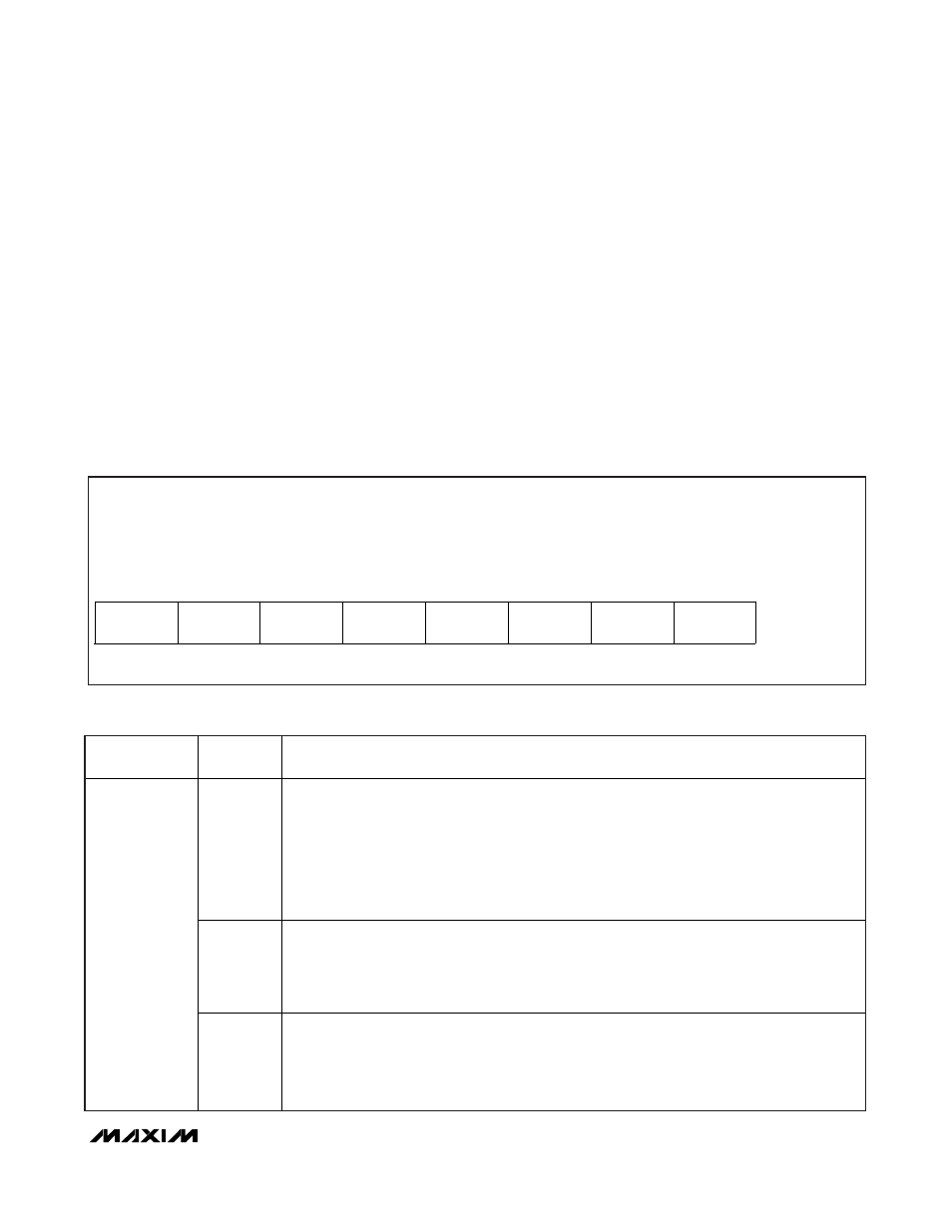
Table 3. chxen Register Format
Description:
Channel enable bits
Register Title:
chxen
Register Address:
0x69
R/W
R/W
R/W
R/W
R/W
R/W
R/W
R/W
RESET
VALUE
Ch4_EN2
Ch4_EN1
Ch3_EN2
Ch3_EN1
Ch2_EN2
Ch2_EN1
Ch1_EN2
Ch1_EN1
AA (HWEN
= high)
bit 7
bit 6
bit 5
bit 4
bit 3
bit 2
bit 1
bit 0
00 (HWEN
= low)