Table 29. prot input and prot[] bits – Rainbow Electronics MAX5961 User Manual
Page 29
MAX5961
0 to 16V, Quad, Hot-Swap Controller
with 10-Bit Current and Voltage Monitor
______________________________________________________________________________________
29
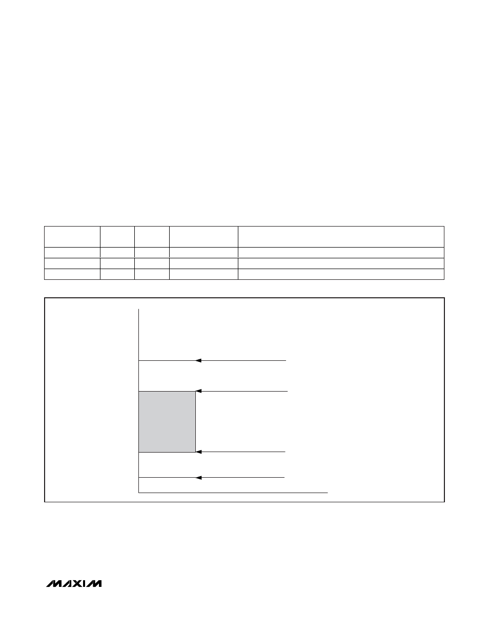
If PG_ is asserted and the voltage is outside the warn-
ing limits, the ALERT output is asserted low. Depending
on the status of the prot[] bits in register status1[7:6],
the MAX5961 can also deassert the PG_ output or turn
off the external MOSFET when the voltage is outside the
critical limits (see Figure 4). Table 29 shows the behav-
ior for the three possible states of the PROT input. Note
that the PROT input does not affect the MAX5961
response to the UV or OV warning digital comparators;
it only determines the system response to the critical
digital comparators (see Tables 4a, 4b, and 29).
In a typical application, the UV1 and OV1 thresholds
would be set closer to the nominal output voltage, and
the UV2 and OV2 thresholds would be set further from
nominal (see Figure 4). This provides a “progressive”
response to a voltage excursion. However, the thresh-
olds can be configured in any arrangement or combi-
nation as desired to suit a given application.
Table 29. PROT Input and prot[] Bits
PROT INPUT
STATE
prot[1]
prot[0]
UV/OV WARNING
ACTION
UV/OV CRITICAL ACTION
Unconnected
0
0
Assert ALERT
Assert ALERT
High
0
1
Assert ALERT
Assert ALERT, clear PG_
Low
1
0
Assert ALERT
Assert ALERT, clear PG_, and shutdown channel(s)
Figure 4. Graphical Representation of Typical UV and OV Thresholds Configuration
OV2 "CRITICAL" THRESHOLD
UV2 "CRITICAL" THRESHOLD
UV1 "WARNING" THRESHOLD
OV1 "WARNING" THRESHOLD