Table 5a. ifast2slow register format – Rainbow Electronics MAX5961 User Manual
Page 19
MAX5961
0 to 16V, Quad, Hot-Swap Controller
with 10-Bit Current and Voltage Monitor
______________________________________________________________________________________
19
Startup
When all conditions for channel turn-on are met, the
external n-channel MOSFET switch is fully enhanced
with a typical gate-to-source voltage of 5.5V to ensure a
low drain-to-source resistance. The charge pump at
each GATE_ driver sources 5µA to control the output-
voltage turn-on slew rate. An external capacitor can be
added from GATE_ to GND_ to further reduce the volt-
age slew rate. Placing a 1kΩ resistor in series with this
capacitance will prevent the added capacitance from
increasing the gate turn-off time; see the
Typical
Application Circuit
. Total inrush current is the load cur-
rent summed with the product of the gate voltage slew
rate dv/dt and the load capacitance.
To determine the output dv/dt during startup, divide the
GATE_ pullup current I
G(UP)
by the gate-to-ground
capacitance. The voltage at the source of the external FET
follows the gate voltage, so the load dv/dt is the same as
the gate dv/dt. Inrush current is the product of the dv/dt
and the load capacitance. The time to start up t
SU
is the
hot-swap voltage VS_ divided by the output dv/dt.
Be sure to choose an external MOSFET that can handle
the power dissipated during startup. The inrush current
is roughly constant during startup, and the voltage drop
across the FET (drain to source) decreases linearly as
the load capacitance charges. The resulting power dissi-
pation is therefore roughly equivalent to a single pulse of
magnitude (VS_ x I_
INRUSH
)/2 and duration t
SU
. Refer to
the thermal resistance charts in the MOSFET data sheet
to determine the junction temperature rise during startup,
and ensure that this does not exceed the maximum junc-
tion temperature for worst-case ambient conditions.
Circuit-Breaker Protection
As the channel is turned on and during normal opera-
tion, two analog comparators are used to detect an
overcurrent condition by sensing the voltage across an
external resistor connected between SENSE_ and
MON_. If the voltage across the sense resistor is less
than the slow-trip and fast-trip circuit-breaker thresh-
olds, the GATE_ output remains high. If either of the
thresholds are exceeded due to an overcurrent condi-
tion, the gate of the MOSFET is pulled down to MON_
by an internal 500mA current source.
The higher of the two comparator thresholds, the fast-
trip, is set by an internal 8-bit DAC (see Table 8), within
one of three configurable full-scale current-sense
ranges: 25mV, 50mV, or 100mV (see Tables 7a and
7b). The 8-bit fast-trip threshold DAC can be pro-
grammed from 40% to 100% of the selected full-scale
current-sense range. The slow-trip threshold follows the
fast-trip threshold as one of four programmable ratios,
set by the ifast2slow register (see Tables 5a and 5b).
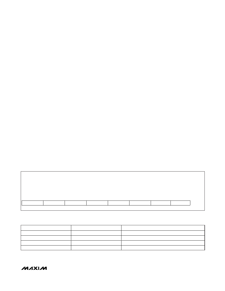
Table 5a. ifast2slow Register Format
Description:
Fast-trip to slow-trip threshold ratio setting bits
Register Title:
ifast2slow
Register Address:
0x5E
R/W
R/W
R/W
R/W
R/W
R/W
R/W
R/W
RESET
VALUE
Ch4_FS1
Ch4_FS0
Ch3_FS1
Ch3_FS0
Ch2_FS1
Ch2_FS0
Ch1_FS1
Ch1_FS0
0xFF
bit 7
bit 6
bit 5
bit 4
bit 3
bit 2
bit 1
bit 0
Table 5b. Setting Fast-Trip to Slow-Trip Threshold Ratio
Chx_FS1
Chx_FS0
FAST-TRIP TO SLOW-TRIP RATIO (%)
0
0
125
0
1
150
1
0
175
1
1
200