Pin description (continued) – Rainbow Electronics MAX5961 User Manual
Page 10
MAX5961
0 to 16V, Quad, Hot-Swap Controller
with 10-Bit Current and Voltage Monitor
10
______________________________________________________________________________________
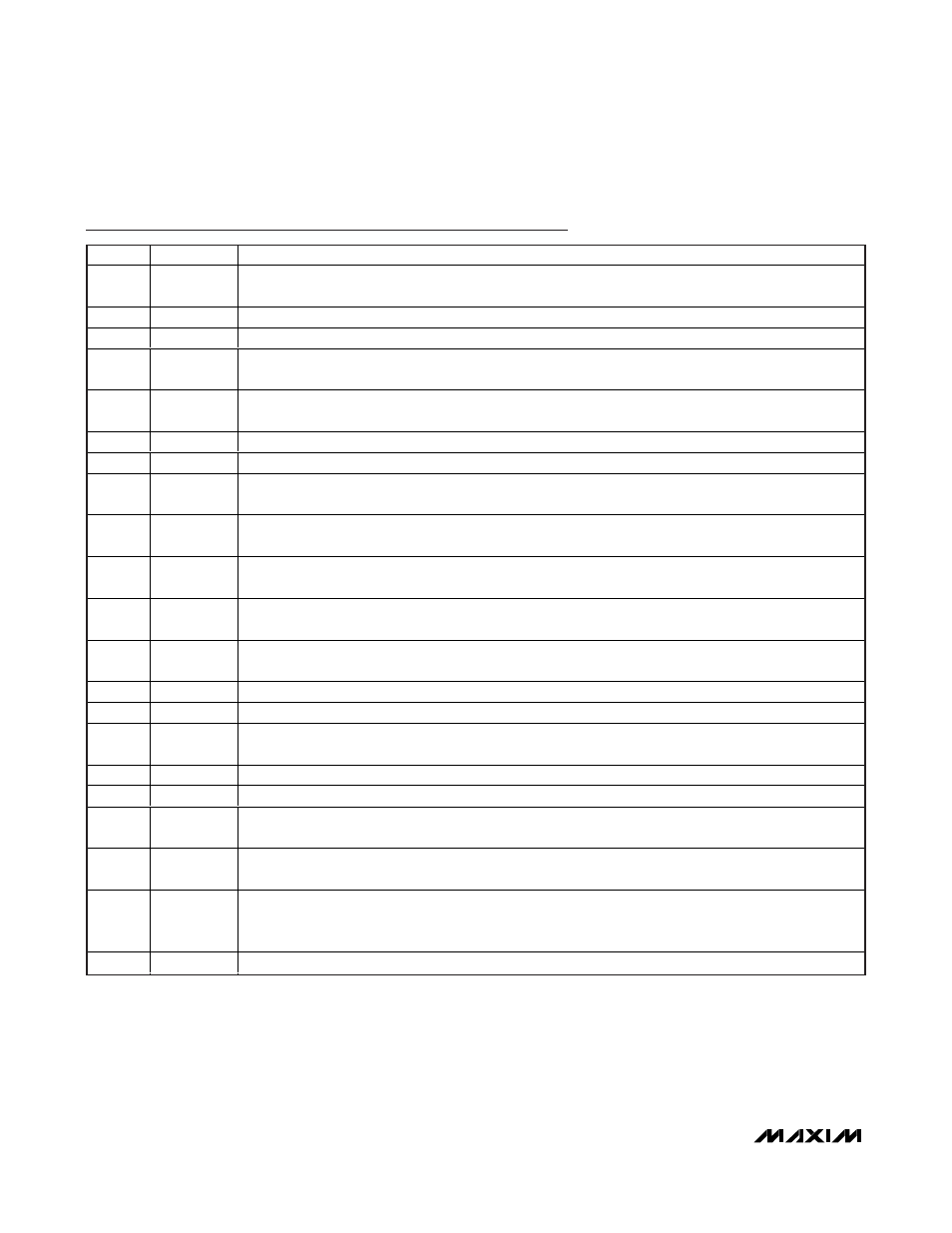
Pin Description (continued)
PIN
NAME
FUNCTION
29
SENSE4
Channel 4 Current-Sense Input. Connect SENSE4 to the source of an external MOSFET and to one end of
R
SENSE4
(see the Typical Application Circuit).
30
MON4
Channel 4 Voltage Monitoring Input
31
GATE4
Channel 4 Gate-Drive Output. Connect to gate of an external n-channel MOSFET.
32
GND4
Channel 4 Gate Discharge Current Ground Return. Connect all GND_ and DGND to AGND externally
using a star connection.
33
GND2
Channel 2 Gate Discharge Current Ground Return. Connect all GND_ and DGND to AGND externally
using a star connection.
34
GATE2
Channel 2 Gate-Drive Output. Connect to gate of an external n-channel MOSFET.
35
MON2
Channel 2 Voltage Monitoring Input
36
SENSE2
Channel 2 Current-Sense Input. Connect SENSE2 to the source of an external MOSFET and to one end of
R
SENSE2
(see the Typical Application Circuit).
37
ILIM4
Channel 4 Three-State Current-Sense Range Selection Input. Set the circuit-breaker threshold range by
connecting to DGND, DREG, or leave unconnected (see Table 7b).
38
ILIM3
Channel 3 Three-State Current-Sense Range Selection Input. Set the circuit-breaker threshold range by
connecting to DGND, DREG, or leave unconnected (see Table 7b).
39
ILIM2
Channel 2 Three-State Current-Sense Range Selection Input. Set the circuit-breaker threshold range by
connecting to DGND, DREG, or leave unconnected (see Table 7b).
40
ILIM1
Channel 1 Three-State Current-Sense Range Selection Input. Set the circuit-breaker threshold range by
connecting to DGND, DREG, or leave unconnected (see Table 7b).
41
IN
Power-Supply Input. Connect to a voltage from 2.7V to 16V. Bypass to AGND with a 1µF capacitor.
42
AGND
Analog Ground. Connect all GND_ and DGND to AGND externally using a star connection.
43
REG
Internal Regulator Output. Bypass to ground with a 1µF capacitor. Connect only to DREG and logic-input
pullup resistors. Do not use to power external circuitry.
44
A1
Three-State I
2
C Address Input 1
45
A0
Three-State I
2
C Address Input 0
46
PROT
Protection Behavior Input. Three-state input sets one of three different response options for undervoltage
and overvoltage events (see Table 29).
47
MODE
Hot-Swap Three-State Mode Select Input. Connect MODE to DGND, DREG, or leave it unconnected to
operate the hot-swap channels independently, in pairs, or as a group of four, respectively (see Table 2).
48
HWEN
Hardware Enable Input. Connect to DREG or DGND. State is read upon power-up as V
IN
crosses the
UVLO threshold and sets Chx_EN2 bits with this value. After UVLO, this input becomes inactive until
power is cycled.
—
EP
Exposed Pad. EP is internally grounded. Connect externally to AGND.