Installation guide, Installation – Veris Industries H8936 Install User Manual
Page 4
Z202662-0G
PAGE 4
©2012 Veris Industries USA 800.354.8556 or 1.503.598.4564 / [email protected]
09126
Alta Labs, Enercept, Enspector, Hawkeye, Trustat, Veris, and the Veris ‘V’ logo are trademarks or registered trademarks of Veris Industries, L.L.C. in the USA and/or other countries.
TM
H8932/H8936
INSTALLATION GUIDE
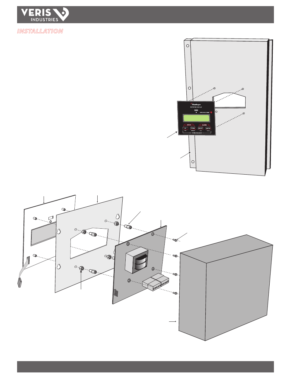
Faceplate (A)
Box Lid (H8936) or Panel (H8932)
(B)
Network Display (E)
(4 ea.) #6-32 Screws (F)
(4 ea.) Threaded Stand-Offs (D)
(4 ea.) Threaded Spacers (C)
(Provided with H8936 only)
Box (G) is provided with the
H8936 only (preassembled)
INSTALLATION
Component List
A. Face Plate with membrane switch ribbon cable
B. Box Lid (H8936 only) or panel (not included with H8932)
C. Threaded spacers (H8936 only)
D. Four threaded stand-offs
E. Network Display
F. Four #6-32 screws
G. Box (H8936 only)
H8932 Mounting in a Panel (see right)
1. Drill 4 holes in the panel and cut out an area for the H8932.
2. Secure the faceplate by screwing the four threaded stand-offs (D) into the face
plate studs from the inside of the door.
3. Attach the Network Display (E) to the threaded studs using four #6-32 screws (F)
provided.
4. Connect the membrane switch ribbon cable to the membrane switch pin
connector.
H8932/H8936 Assembly Example:
Faceplate (A)
Panel (B)