Installation guide, Configuring ct values and setting alarm thresholds, H8238 – Veris Industries H8238 Install User Manual
Page 7
H8238
Z202837-0H
PAGE 7
©2012 Veris Industries USA 800.354.8556 or +1.503.598.4564 / [email protected]
11124
Alta Labs, Enercept, Enspector, Hawkeye, Trustat, Veris, and the Veris ‘V’ logo are trademarks or registered trademarks of Veris Industries, L.L.C. in the USA and/or other countries.
TM
INSTALLATION GUIDE
CONFIGURING CT VALUES AND SETTING ALARM THRESHOLDS
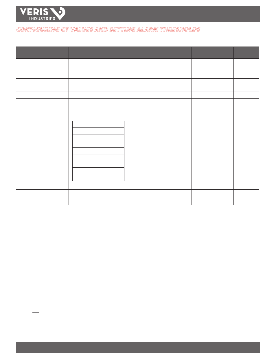
Configure CT values and alarm thresholds with the software configuration utility or by writing to Modbus protocol registers.
Parameter
Description
Register
Number
Range
Default Value
CT Scale
configure the H8238 to the size of the CTs monitoring the service.
30
1-5999 A
100 A
Over Voltage Alarm Threshold
occurs if the average L-L voltage is greater than this threshold at any time
31
0-65535 V*
65535 V
Under Voltage Alarm Threshold
occurs if the average L-L voltage is less than this threshold for at least 1- seconds
32
0-65535 V*
0 V
Over Current Alarm Threshold Register
occurs if any phase current is greater than this threshold at any time
33
0-65535 A*
65535 A
Under Current Alarm Threshold
occurs if any phase current is less than this threshold at any time
34
0-65535 A*
0 A
Over kVA Alarm Threshold Register
occurs if the total apparent power is greater than this threshold at any time
35
0-65535 kVA*
65535 kVA
Under kVA Alarm Threshold
occurs if the total apparent power is less than this threshold at any time
36
0-65535 kVA*
65535 kVA
Meter Alarm Status Register
This register holds in memory any alarm that has occurred in the meter. Conditions that caused
an alarm and then returned to normal states are visible in this register. To clear the latching
alarms, write a 0 to the desired bit.
Bit 0
Over Current
Bit 1
Under Current
Bit 2
Over kVA
Bit 3
Under kVA
Bit 4
Over Voltage
Bit 5
Under Voltage
Bit 6
Phase Loss A
Bit 7
Phase Loss B
Bit 8
Phase Loss C
37
n/a
Phase Loss Threshold
Sets the maximum to deviation of any phase voltage compared the average L-N voltage
38
0-100%
65535 (disabled)
Meter Alarm Status
This register holds the instantaneous state of the meter alarms. Alarms in this register represent
present conditions only.
49
n/a
Non Latching
Modbus Function Codes Supported
3, read holding registers
6, preset single register
17, report slave ID
* Correct conversion to engineering units requires use of integer multiplier. For example: To set
over-voltage threshold (#31) to 235 V:
235V = 2350
0.1
2350 is the value to write to #31