Installation guide, Product diagram, Dimensions – Veris Industries H8238 Install User Manual
Page 2: Product overview, H8238
H8238
Z202837-0H
PAGE 2
©2012 Veris Industries USA 800.354.8556 or +1.503.598.4564 / [email protected]
11124
Alta Labs, Enercept, Enspector, Hawkeye, Trustat, Veris, and the Veris ‘V’ logo are trademarks or registered trademarks of Veris Industries, L.L.C. in the USA and/or other countries.
TM
INSTALLATION GUIDE
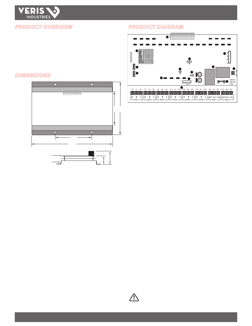
PRODUCT DIAGRAM
1
2
3
3
4
5
6
7
8
9
101
11
12
13
14
1.
Board Connection Ribbon Cable:
Connects the transducer and CT circuit
boards.
2.
Configuration Table:
Easy reference communications configuration chart, silk-
screened on the circuit board.
3.
ALIVE LED:
Flashes once per second to indicate correct operation. If steadily lit,
indicates internal communications diagnostic event.
4.
Sensed Voltage Connection:
Sensed line voltage, common for all meter
channels. 0-480 VAC.
5.
Baud Rate & Parity Selection Switches:
Field selectable parity, baud rate, and
2 or 4 wire communications parameters.
6.
Modbus Address DIP Switches:
Set these switches must be set to assign an
individual Modbus address before connecting the device (see page 7) .
7.
TX LED:
Indicates successful transmission of information over the Modbus
network.
8.
Optical Isolation:
An optical isolation barrier separates high voltage from the
communications network.
9.
RS-485 2 or 4-wire Connection:
Daisy chain multiple H8238s using a 2 or
4-wire Modbus network.
10.
RX LED:
Indicates successful reception of information over the Modbus network.
11.
Power Transformers:
Linear power supply for reliability and low noise.
12.
250 VAC 40mA Slow Blow Fuse:
Fused power connection for circuit protection.
13.
120 or 240 VAC Power Connection*:
Easy 2-wire 120 or 240 VAC line to neutral
50/60 Hz.
14.
5A CT Input Terminals:
Current Transformer (CT) terminals accept any 5 A CT
signal. Two wire, not polarity sensitive.
* For 240 VAC power connection version, use the H8238E or H8238EL.
DIMENSIONS
A
B
D
C
Top View
Side View
WIDTH:
A
5.3”/135mm (board)
B
8.9”/226mm (mounting bracket base)
LENGTH:
C 6.0”/153mm
D 12.8”/325mm
HEIGHT:
E
2.9”/74mm
F 4.0”/101mm
main circuit board
mounting bracket
3
F
E
PRODUCT OVERVIEW
The H8238 multi-circuit meter provides a means of monitoring multiple loads
originating from the same electrical service. The multi-circuit meter can monitor
up to eight 3-phase, 3-wire loads or six 3-phase, 4-wire loads with neutral current
monitoring. With one RS-485 connection, the H8238 provides a Modbus RTU
communications output and 72 alarms for situations such as over/under voltage,
over/under current, and phase loss. Up to 30 devices can be addressed on the same
Modbus network.
DANGER: 5A CTs can present hazardous voltages.
Install CTs in accordance with manufacturer's instructions.
Terminate the CT secondary before applying current.