Installation guide, Ab c, Installation – Veris Industries H8238 Install User Manual
Page 3
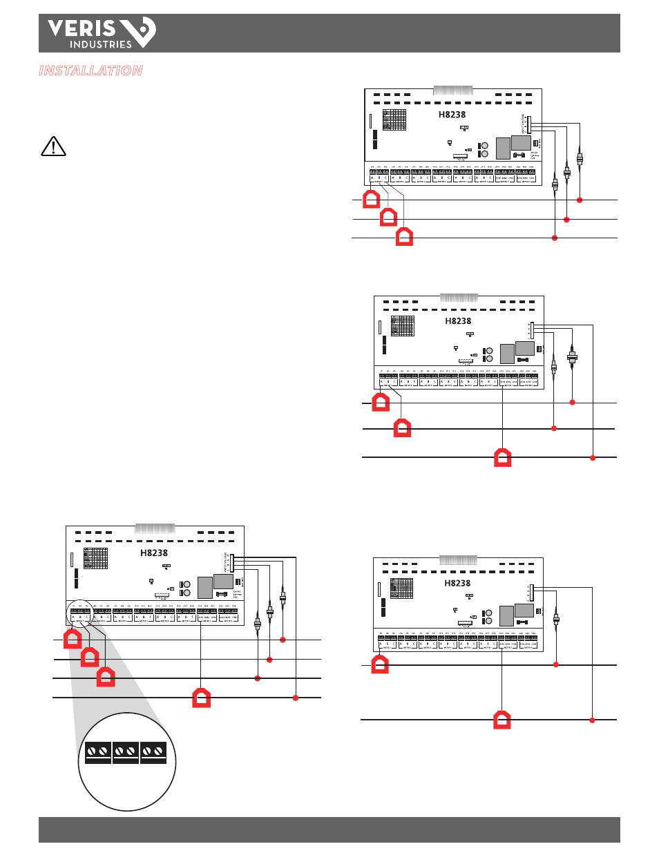
H8238
Z202837-0H
PAGE 3
©2012 Veris Industries USA 800.354.8556 or +1.503.598.4564 / [email protected]
11124
Alta Labs, Enercept, Enspector, Hawkeye, Trustat, Veris, and the Veris ‘V’ logo are trademarks or registered trademarks of Veris Industries, L.L.C. in the USA and/or other countries.
TM
INSTALLATION GUIDE
*
A
B
C
N
JP1
JP2
METER 1
JP3
A
B
C
Neutral current
monitoring optional
3-Phase 4-Wire Installation
3-Phase 3-Wire Installation
A
B
C
1-Phase 3-Wire Installation
†
1-Phase 2-Wire Installation
†
HOT
N
*
HOT
120V
HOT
N
*
Neutral current
monitoring optional
Neutral current
monitoring optional
† Phase loss, Under Current & Under Voltage alarms are active when
monitoring single phase loads.
INSTALLATION
Disconnect and lock out power to the device.
Current Configuration
DANGER: 5A CTs can present hazardous voltages.
Install CTs in accordance with manufacturer's instructions.
Terminate the CT secondary before applying current.
1. Connect the current inputs. The multi-circuit meter is capable of monitoring up to
eight 3Ø 3-wire circuits or six 3Ø circuits plus neutral current. Choose either 8 or 6
meter configuration and proceed to either step 2 or 3, as appropriate.
2. Eight 3Ø 3-Wire Circuit Monitoring Mode: Connect 5 Amp CTs to terminal blocks
JP1 through JP24. The JP terminal blocks are two position, not polarity sensitive,
and compatible with standard 2-wire 5 Amp CT outputs. Connect each monitored
service to the JP terminals within a meter set. For example meter #1 CT inputs are
labeled JP1 (PhA), JP2(PhB), & JP3(PhC). Connect the CT monitoring phase A for
metered service to the first JP in its set.
3. Six 3Ø 4-Wire Circuit Monitoring Mode: Connect 5 Amp CTs to terminal blocks
JP1 through JP24. The JP terminal blocks are two position, not polarity sensitive,
and compatible with standard 2-wire 5 Amp CT outputs. Connect each monitored
service to the JP terminals within a meter set. For example meter #1 CT inputs are
labeled JP1 (PhA), JP2 (PhB), & JP3 (PhC). Connect the CT monitoring phase A for
metered service to the first JP in its set. The terminal blocks referenced by meter 7
and meter 8 are used to monitor neutral currents. Wire the CT monitoring neutral
current for the service monitored by METER 1 to JP19. Wire the CT monitoring
neutral current for the service monitored by METER 2 to JP20. Wire the CT
monitoring neutral current for the service monitored by METER 3 to JP21 and so
on through JP24.
4. Connect the voltage leads to the phase conductors as shown in the wiring
examples on this page. The monitored voltage must be common to all services
monitored by the CTs installed previously.