Veris Industries H8238 Install User Manual
H8238, Danger, Notice
POWER MONITORING
Z202837-0H
PAGE 1
©2012 Veris Industries USA 800.354.8556 or +1.503.598.4564 / [email protected]
11124
Alta Labs, Enercept, Enspector, Hawkeye, Trustat, Veris, and the Veris ‘V’ logo are trademarks or registered trademarks of Veris Industries, L.L.C. in the USA and/or other countries.
TM
INSTALLATION GUIDE
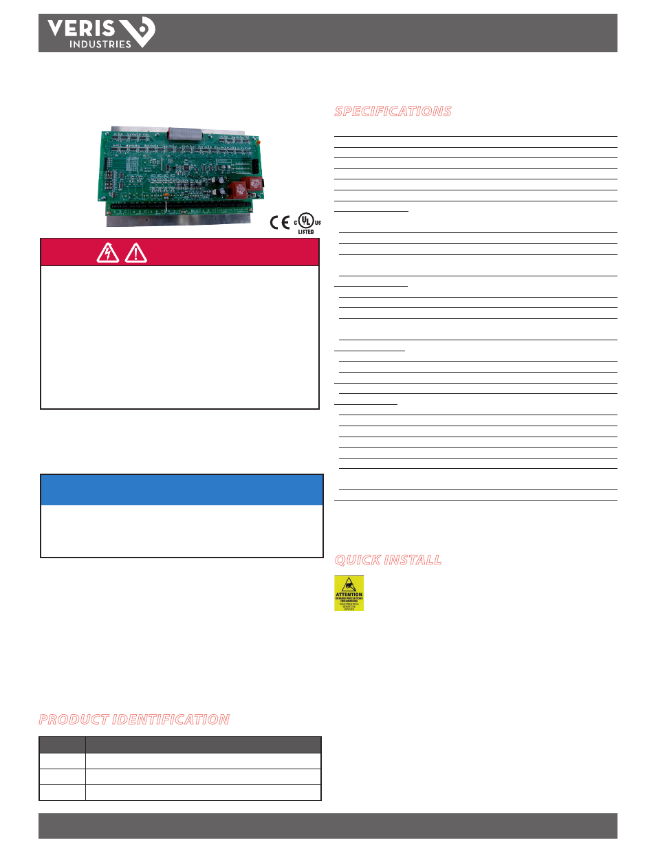
H8238
Multi-Circuit Meter
HAZARD OF ELECTRIC SHOCK, EXPLOSION, OR ARC FLASH
• Follow safe electrical work practices. See NFPA 70E in the USA, or applicable local codes.
• This equipment must only be installed and serviced by qualified electrical personnel.
• Read, understand and follow the instructions before installing this product.
• Turn off all power supplying equipment before working on or inside the equipment.
• Use a properly rated voltage sensing device to confirm power is off.
DO NOT DEPEND ON THIS PRODUCT FOR VOLTAGE INDICATION
• SECONDARY LEADS/TERMINALS OF CURRENT OUTPUT (e.g. 5A) CTs MUST BE SHORTED,
OR CONNECTED TO THE BURDEN AT ALL TIMES.
• Only install this product on insulated conductors.
Failure to follow these instructions will result in death or serious injury.
DANGER
A qualified person is one who has skills and knowledge related to the construction and
operation of this electrical equipment and the installation, and has received safety
training to recognize and avoid the hazards involved.
NEC2009 Article 100
No responsibility is assumed by Veris Industries for any consequences arising out of the
use of this material.
NOTICE
• This product is not intended for life or safety applications.
• Do not install this product in hazardous or classified locations.
• The installer is responsible for conformance to all applicable codes.
• Mount this product inside a suitable fire and electrical enclosure.
FCC PART 15 INFORMATION
NOTE: This equipment has been tested by the manufacturer and found
to comply with the limits for a class A digital device, pursuant to part
15 of the FCC Rules. These limits are designed to provide reasonable
protection against harmful interference when the equipment is
operated in a commercial environment. This equipment generates,
uses, and can radiate radio frequency energy and, if not installed and
used in accordance with the instruction manual, may cause harmful
interference to radio communications. Operation of this equipment in
a residential area is likely to cause harmful interference in which case
the user will be required to correct the interference at his own expense.
Modifications to this product without the express authorization of
Veris Industries nullify this statement.
SPECIFICATIONS
Electrical Services
Eight 3Ø circuits sharing a common line voltage source
Sample Rate
1280 Hz
Operating Temperature Range
0° to 60°C (32° to 140°F) (<95% RH, non-condensing)
Storage Temperature Range
-40°C to 70°C (-40° to 158°F)
Altitude of Operation
3 km
Systems Accuracy
+/- 1% (target, exclusive of user-supplied CTs)*
Variable Update Rate
200 msec for voltages, 1.6 sec for all others
Measured Voltage Inputs:
Number of Channels
Three (phase A, B, C, plus neutral). Average of phases used
for
L-N values if no neutral present
Maximum Voltage
277VAC L-N +10%; 480VAC L-L +10%
Frequency
50/60 Hz
Terminal Block
4-position Euro style pluggable connector (max. wire size 12 gauge);
torque
5.7 in•b (0.64 N•m)
Measured Current Inputs:
Number of Channels
24 (8 meters x 3 phases/meter)
CT Input Type
5 Amp (customer-supplied)
CT Range
Each of 8 meters independently adjustable from 1A:5A to 9999A:5A
Terminal Block
6-position Euro style cage clamp connector (max. wire size 14 gauge);
torque
4.4 in•lb (0.50 N•m)
Operating Power Inputs:
Power Source
Dedicated 120VAC L-N (H8238) or 240VAC L-N (H8238E); fused 40 mA
Power Voltage Tolerance
+10/-25%
Frequency
50/60 Hz
Terminal Block
2-position Euro style pluggable connector (max. wire size 12 gauge)
Network Connections:
Type
Modbus RTU
Connection
DIP switch-selectable 2-wire or 4-wire
Address
DIP switch-selectable base address (1 to 233 in steps of 8)
Baud Rate
DIP switch-selectable 2400, 4800, 9600, 19200**
Parity
DIP switch-selectable NONE, ODD, EVEN
Communication Format
8-data-bits, 1-start-bit, 1-stop-bit
Terminal Block
5-position Euro style pluggable connector (max. wire size 12 gauge);
nominal
torque 4.0 in•lb (0.45 N•m); maximum torque 5.0 in•lb (0.56 N•m)
Installation Category
Cat III, pollution degree 2
* Accuracy specification valid only when amperages are greater than 10% of maximum CT range.
** Baud rates for H8238EL are 1200, 2400, 4800, and 9600.
QUICK INSTALL
Observe precautions for handling static sensitive
devices to avoid damage to the circuitry that
is not covered under the factory warranty.
1. Connect the current inputs.
2. Connect the voltage leads.
3. Configure the communication switches.
4. Select a network address.
5. Connect the RS-485 connection to the communications wiring.
6. Connect the circuit power.
PRODUCT IDENTIFICATION
MODEL
DESCRIPTION
H8238
Multi-Circuit Monitor, 90-130 VAC supply voltage
H8238E
Multi-Circuit Monitor, 240 VAC supply voltage
H8238EL
Multi-Circuit Monitor, 240 VAC supply voltage, low baud rate version