Installation guide, Wiring, Wire 4-wire 2-wire example – Veris Industries E30 Install User Manual
Page 7: Shield rx- tx- rx+ tx+ tx- tx
Z204998-0N
PAGE 7
©2013 Veris Industries USA 800.354.8556 or +1.503.598.4564 / [email protected]
01131
TM
E30
INSTALLATION GUIDE
Alta Labs, Enercept, Enspector, Hawkeye, Trustat, Aerospond, Veris, and the Veris ‘V’ logo are trademarks or registered trademarks of Veris Industries, L.L.C. in the USA and/or other countries.
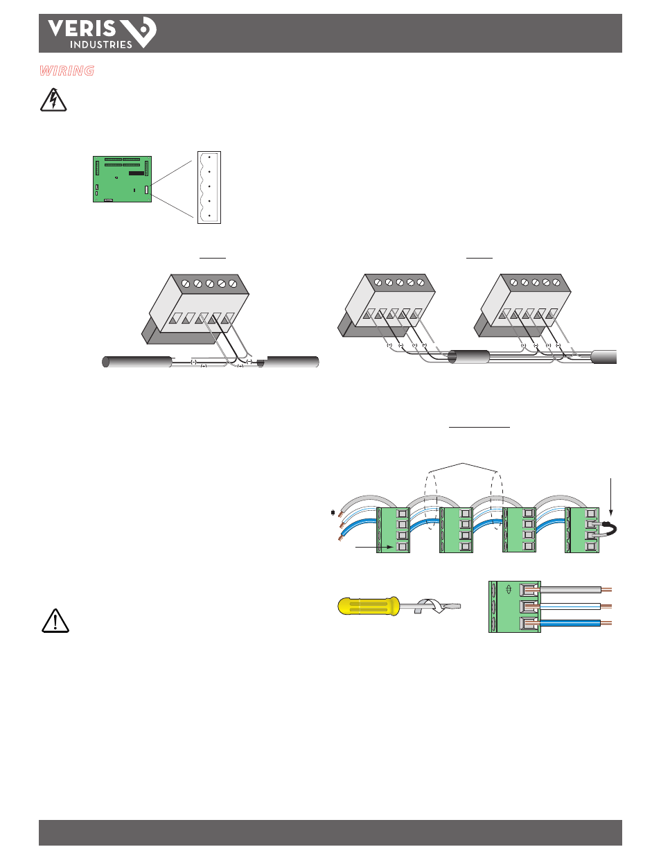
WIRING
Disconnect and lock out power before making any wiring connections.
Connect 2-wire or 4-wire Modbus RS-485 daisy chain network (Figures 10 and 11).
Figure 10
Figure 11
SHIELD
RX- TX-
RX+ TX+
TX-
TX+
Master or Slave
SHLD
TX+
TX+
RX+
TX–
TX-
RX-
SHIELD
SHIELD
Master
Slave
SHLD
TX+
TX+
RX+
TX–
TX-
RX-
SHIELD
SHLD
TX+
TX+
RX+
TX–
TX-
RX-
SHIELD
2-Wire
4-Wire
2-Wire Example
Figure 12
–
+
Belden 1120A or
equivalent
120 Ω terminator
on last device of
daisy chain
Not Used
WARNING: After wiring the RS-485 cable, remove all
scraps of wire or foil shield from the electrical panel.
Wire scraps coming into contact with high voltage
conductors could be DANGEROUS!
–
+
1. Mechanically secure the RS-485 cable where it enters the electrical panel.
2. Connect all RS-485 devices in a daisy-chain fashion, and properly terminate the
chain (Figure 12).
3. Shield the RS-485 cable using twisted-pair wire, such as Belden 1120A. Use cable
that is voltage-rated for the installation.
4. When tightening terminals, ensure that the correct torque is applied: 0.5 to 0.6
N·m (0.37 to 0.44 ft·lb ) for the connectors on data acquisition board, 0.22 to 0.26
N·m (0.16 to 0.19 ft·lb) for the connectors on the adapter boards (Figure 13).
Figure 13