Installation guide, Installation – Veris Industries E30 Install User Manual
Page 4
Z204998-0N
PAGE 4
©2013 Veris Industries USA 800.354.8556 or +1.503.598.4564 / [email protected]
01131
TM
E30
INSTALLATION GUIDE
Alta Labs, Enercept, Enspector, Hawkeye, Trustat, Aerospond, Veris, and the Veris ‘V’ logo are trademarks or registered trademarks of Veris Industries, L.L.C. in the USA and/or other countries.
E30 CURRENT SENSOR STRIP
E30 CURRENT SENSOR STRIP
E30 CURRENT SENSOR STRIP
E30 CURRENT SENSOR STRIP
20
20
20
20
20
20
20
20
20
2020
20
20
20
20
20
20
20
20
20
20
20
INSTALLATION
Observe precautions for handling static sensitive
devices to avoid damage to the circuitry that
is not covered under the factory warranty.
Disconnect and lock out power to the electrical panel.
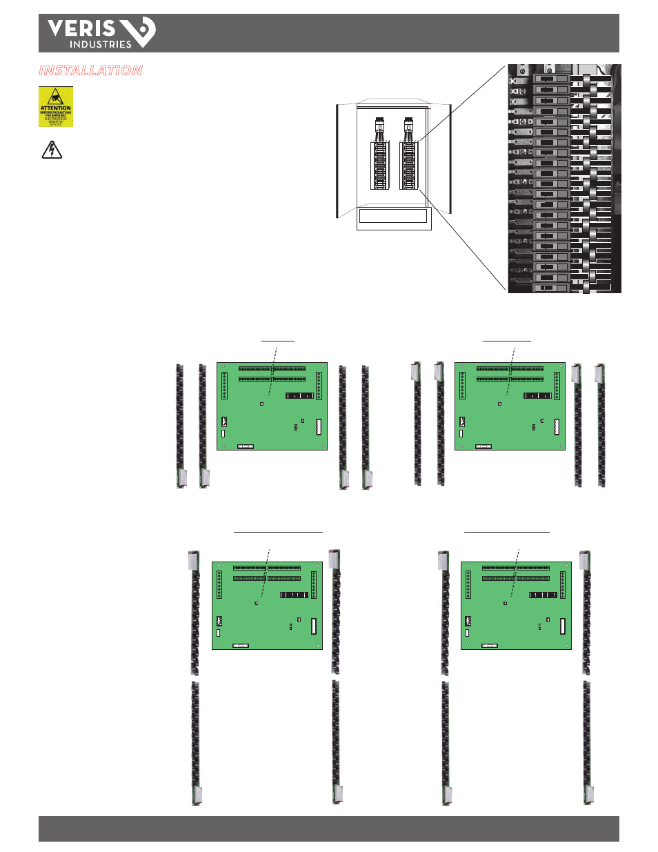
1. Install the current sensor strips in the panel (Figure 1).
2. Arrange the sensor strips in one of the four configurations shown in Figure 2.
Adjust orientation of the circuit numbers in the field during commissioning by
writing to Modbus Register 6 or use free configuration software at www.veris.
com.
Figure 1
Current sensors accept a maximum #2 AWG
(0.384” O.D.) wire with THHN insulation.
Use this gauge wire or smaller for 100 A circuits.
A
B
A
B
A
B
A
B
Panel 1
Panel 2
1
5
9
13
17
21
25
29
33
37
41
3
7
11
15
19
23
27
31
35
39
2
6
10
14
18
22
26
30
34
38
42
4
8
12
16
20
24
28
32
36
40
A
B
A
B
1
5
9
13
17
21
25
29
33
37
41
3
7
11
15
19
23
27
31
35
39
2
6
10
14
18
22
26
30
34
38
42
4
8
12
16
20
24
28
32
36
40
1
5
9
13
17
21
25
29
33
37
41
3
7
11
15
19
23
27
31
35
39
2
6
10
14
18
22
26
30
34
38
42
4
8
12
16
20
24
28
32
36
40
A
B
A
B
1
5
9
13
17
21
25
29
33
37
41
3
7
11
15
19
23
27
31
35
39
2
6
10
14
18
22
26
30
34
38
42
4
8
12
16
20
24
28
32
36
40
1
3
5
7
9
11
13
15
17
19
21
2
4
6
8
10
12
14
16
18
20
1
3
5
7
9
11
13
15
17
19
21
2
4
6
8
10
12
14
16
18
20
22
24
26
28
30
32
34
36
38
40
42
23
25
27
29
31
33
35
37
39
41
22
24
26
28
30
32
34
36
38
40
42
23
25
27
29
31
33
35
37
39
41
2
6
10
14
18
22
26
30
34
38
42
4
8
12
16
20
24
28
32
36
40
2
6
10
14
18
22
26
30
34
38
42
4
8
12
16
20
24
28
32
36
40
1
5
9
13
17
21
25
29
33
37
41
3
7
11
15
19
23
27
31
35
39
1
5
9
13
17
21
25
29
33
37
41
3
7
11
15
19
23
27
31
35
39
A
B
A
B
A
B
A
B
Panel 1
Panel 2
Panel 1
Panel 2
Panel 1
Panel 2
A
B
A
B
A
B
A
B
Top Feed
Bottom Feed
Single Row: Sequential
Single Row: Odd/Even
Register 6
Value = 0
(Default)
Register 6
Value = 1
Register 6
Value = 2
Register 6
Value = 3
Figure 2
The examples in this graphic show
the 21 current sensor strips strips.
The same configuration options are
available for the 18 and 12 strips.