Installation guide, Product overview, Dimensions – Veris Industries E30 Install User Manual
Page 2: Quick install, Product identification, Circuit board and mounting bracket, Solid-core current sensor strips, Ct option, Description, Of cts
Z204998-0N
PAGE 2
©2013 Veris Industries USA 800.354.8556 or +1.503.598.4564 / [email protected]
01131
TM
E30
INSTALLATION GUIDE
Alta Labs, Enercept, Enspector, Hawkeye, Trustat, Aerospond, Veris, and the Veris ‘V’ logo are trademarks or registered trademarks of Veris Industries, L.L.C. in the USA and/or other countries.
PRODUCT OVERVIEW
The E30 Series Branch Current Monitor is a device designed to measure the current,
voltage, and energy consumption of up to 92 circuits (84 branch circuits, 2 3-phase
mains, 2 neutrals) on a single board. It increases the board’s current monitoring
capability by combining the functions of two boards into one device.
The E30 consists of a data acquisition board and up to four 21-unit current sensor
strips, with eight auxiliary inputs. The strips are mounted on each side of the panel
board along the termination points of each breaker. The conductor passes through
the appropriate current sensor before terminating at the breaker. Each strip transmits
the current data to the data acquisition board.
Data is transmitted using an RS-485 Modbus protocol. Each data acquisition board
requires two addresses, one for each set of two current sensor strips and four
auxiliary inputs. Data is updated roughly every two seconds. As a circuit approaches
the user-defined threshold, the E30 activates the alarm indicators.
The E30A measures both current and power for the mains and branch circuits. The
E30B measures both current and power for the mains, and current only in each circuit.
The E30C measures current only for the mains and branch circuits.
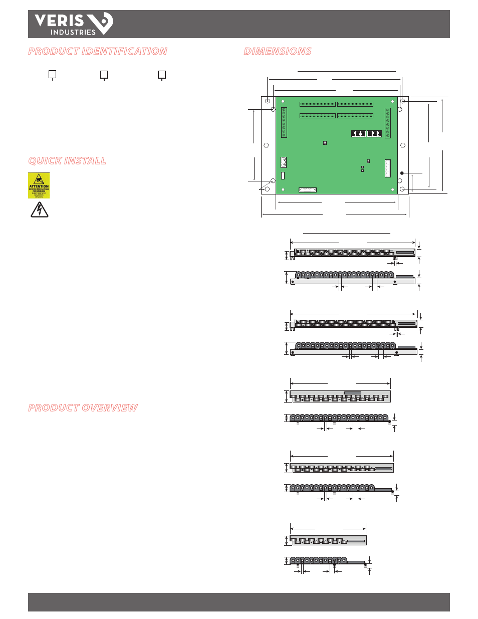
DIMENSIONS
Circuit Board and Mounting Bracket
7.3”
(184 mm)
8.9”
(288 mm)
5.8”
(146 mm)
4.8”
(122 mm)
3.9”
(100 mm)
7.9”
(200 mm)
8.3”
(211 mm)
1.75”
(45 mm)
Ø = 0.2”
(5 mm)
Solid-Core Current Sensor Strips
0.4” (10 mm)
opening
1.0” (26 mm)
on center
25.0” (635 mm)
1.2”
(31 mm)
20.3” (516 mm)
1.1”
(28 mm)
0.8”
(20 mm)
0.8”
(20 mm)
1.3”
(33 mm)
2.0”
(50 mm)
slot: 0.25” x 0.5”
(7 x 13mm)
2.0”
(50 mm)
1.7”
(43 mm)
21.2”
(0.9 mm)
1.3”
(32 mm)
slot: 0.25” x 0.5”
(7 x 13mm)
1.2”
(30 mm)
0.4” (10 mm)
opening
0.75” (19 mm)
on center
16.4” (417 mm)
1.7”
(43 mm)
0.4” (10 mm)
opening
0.7” (18 mm)
on center
2.0”
(50 mm)
21.2”
(0.9 mm)
1.3”
(32 mm)
15.7” (399 mm)
0.4” (10 mm)
opening
0.7” (18 mm)
on center
21.2”
(0.9 mm)
1.3”
(32 mm)
12.3” (312 mm)
0.4” (10 mm)
opening
0.7” (18 mm)
on center
QUICK INSTALL
Observe precautions for handling static sensitive
devices to avoid damage to the circuitry that
is not covered under the factory warranty.
Disconnect and lock out power. Use a properly rated
voltage sensing device to confirm the power is off.
1. Mount the current sensor strips adjacent to the breaker terminations.
2. Verify that the serial numbers on the current sensor strips match the
serial number on the data acquisition board.
3. Configure communication and addressing parameters using the DIP switches.
4. Mount the data acquisition board in the electrical enclosure.
5. Connect the current sensor strip cables to the main board, observing the 2-strip or
4-strip setup and their orientation (A or B) within the panel.
6. Wire the RS-485 communications.
7. Connect the CTs to the auxiliary inputs and connect them to the main conductors
in the enclosure (optional).
8. Wire the control power and voltage taps (E30A and E30B only).
9. Download the free E3x configuration tool from www.veris.com to commission the
device for operation.
PRODUCT IDENTIFICATION
E30
CT Option
0 = 100A, ¾" spacing
1 = 100A, 1" spacing
2 = 100A, 18 mm spacing
Description
A = Advanced
B = Intermediate
C = Basic
# of CTs
24 = 2 strips with 12 sensors each*
36 = 2 strips with 18 sensors each*
42 = 2 strips with 21 sensors each
48 = 4 strips
with 12 sensors each*
72 = 4 strips with 18 sensors each*
84 = 4 strips with 21 sensors each
* This option available with
18 mm spacing only.
3/4"
option,
21 CTs
1”
option,
21 CTs
18 mm
option,
18 CTs
18 mm
option,
12 CTs
18 mm
option,
21 CTs