Ab b, Installation guide, Data output – Veris Industries E30 Install User Manual
Page 3: Blink codes for status led, Solid-core current sensor accuracy, Product diagram
Z204998-0N
PAGE 3
©2013 Veris Industries USA 800.354.8556 or +1.503.598.4564 / [email protected]
01131
TM
E30
INSTALLATION GUIDE
Alta Labs, Enercept, Enspector, Hawkeye, Trustat, Aerospond, Veris, and the Veris ‘V’ logo are trademarks or registered trademarks of Veris Industries, L.L.C. in the USA and/or other countries.
DATA OUTPUT
Monitoring at Mains
E30A
E30B
E30C
Current per phase
Max. current per phase
Current demand per phase
Max. current demand per phase
Energy (kWh) per phase
Real Power (kW) per phase
Apparent Power (kVA)
Power factor total *
Power factor per phase
Voltage - L-L and average
Voltage - L-N and average
Frequency (phase A)
Monitoring at Branch Circuit
Current
Max. current
Current demand
Max. current demand
Real power (kW)
Real power (kW) demand
Real power (kW) demand max.
Energy (kWh) per circuit
Power factor
Apparent Power (kVA)
Modbus Alarms
Voltage over/under
Current over/under
* Based on a 3-phase breaker rotation.
BLINK CODES FOR STATUS LED
Color and Pattern
Status Description
Green, once per second
Normal operation
Amber, once per second
Volts or Amps clipping
Amber, twice per second
Invalid firmware image
Amber, three per second
Incorrect strips or strip order
Red, solid or blink
Diagnostic event detected
SOLID-CORE CURRENT SENSOR ACCURACY
100A Solid-Core CT
Voltage Rating
300 VAC
Accuracy
±0.5%
Temperature
0° to 60°C
Agency
UL508 recognized, EN61010
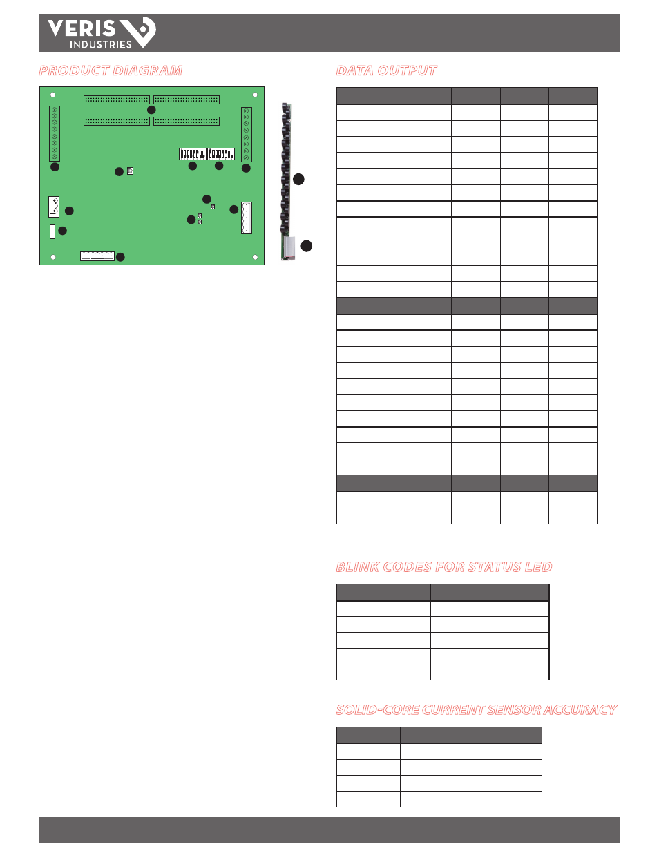
PRODUCT DIAGRAM
7
1
2
3
4
5
6
2
8
9
10
A
A
B
B
11
1.
50-Pin Ribbon Cable Connectors (Data Acquisition Board):
48-inch (1220
mm) ribbon cables are provided for easy connection of current sensor strips to
this point of the data acquisition board. The two connectors on the left are for
panelboard 1; the two on the right are for panelboard 2.
Connect current sensor strips to the correct ribbon cable connectors for each
panel. The top connector is for Strip A, and the bottom conector is for Strip B.
Verify that the serial numbers on the current sensor strips match the
serial number on the data acquisition board.
2.
Auxiliary Inputs:
These 0.333 VAC inputs are used for monitoring the main
breaker or other high amperage source. Inputs on the left are for panelboard 1;
inputs on the right are for panelboard 2.
3.
Control (Mains) Power Connection:
Easy 2-wire 90-277 VAC 50/60 Hz
connection.
4.
Control Power Fuse:
600 VAC, 500 mA time lag, factory-replaceable.
5.
Alive LED:
Red/green/amber LEDs. Blink codes are on page 3.
6.
Voltage Taps:
1, 2, or 3 phase plus neutral connections. For voltage sensing and
power calculations (no voltage taps on the E30C).
7.
Communications Address DIP Switches:
Each Modbus device must have a
unique address. Switches are binary weighted. Left-most switch has a value of 1;
right-most switch has a value of 128. Note: the 4-strip model uses 2 addresses.
8.
Communications Settings DIP Switch:
Configures baud rate, parity, 2/4 wire
communications.
9.
RS-485 2 Connection:
Used for Modbus serial communications. The Universal
plug accomodates 2 or 4 wire connections.
10.
RS-485 LEDs:
The RX LED (closest to DIP switches) indicates the RS-485
is receiving information; the TX LED (farthest from DIP switches) indicates
transmission of information.
11.
Power LED:
Indicates power to main board
12.
Current Sensors:
Each current sensor is capable of monitoring conductors rated
up to a maximum of 100 amps.
13.
50 Pin Ribbon Cable Connectors (Current Sensor Strips):
Connects current
signal from the sensor strip to the main board via the ribbon connectors.
12
13