Installation guide, Strip version 4-strip version, Apanel 1 panel 2 a b b – Veris Industries E30 Install User Manual
Page 5
Z204998-0N
PAGE 5
©2013 Veris Industries USA 800.354.8556 or +1.503.598.4564 / [email protected]
01131
TM
E30
INSTALLATION GUIDE
Alta Labs, Enercept, Enspector, Hawkeye, Trustat, Aerospond, Veris, and the Veris ‘V’ logo are trademarks or registered trademarks of Veris Industries, L.L.C. in the USA and/or other countries.
3. Verify that the serial numbers printed on the current strip and on the data
acquisition board match. The board and the strip are sold as a calibrated set.
4. Configure communication and addressing parameters using DIP switches. The
E30 requires two addresses, one for each set of two current sensor strips and four
auxiliary inputs. See the Configuration section on page 7 for more information.
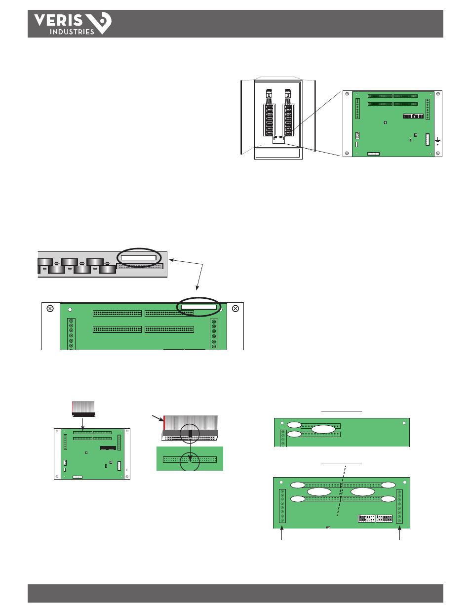
5. Install the E30 acquisition board mounting bracket in the panel using screws and
bolts provided (Figure 3). A grounding connection is located on the mounting
bracket, near the lower right corner. Use this stud to ground the bracket when it is
mounted on a nonconductive surface.
6. Check the labels on the current sensor strip and on the data acquisition board
to make sure the serial numbers match. Additionally, the label indicates which
connector to use on the data acquisition board (e.g. connect the strip labeled
“Panel 1A” to the top left connector on the board; Figure 4). When the device is
powered, if the current sensor strips are installed incorrectly, the Alive LED blinks
amber, three times per second. Check the labels and correct the connections.
E30 CURRENT SENSOR STRIP
E30 CURRENT SENSOR STRIP
E30 CURRENT SENSOR STRIP
E30 CURRENT SENSOR STRIP
Panel 1
Panel 2
Figure 3
Figure 5
Figure 6
2-Strip Version
4-Strip Version
Panel 1 uses base Modbus address as set by DIP switches.
Panel 2 uses base + 1 Modbus address as set by DIP switches.
Align ribbon cable key with
connector keyhole.
Orient ribbon cable so that the
red stripe is on the left side of
the connector.
Panel 2
Panel 1
A
A
B
B
L1 L2 L3 N
Panel 1
A
B
Panel 2 Mains
Panel 1 Mains
Red Stripe
A
Panel 1
Panel 2
A
B
B
Serial numbers on board and strips must match.
Connect strips only to the connector designated
on the label (e.g. 1A).
7. Connect current sensor ribbon cables to the 50-pin connectors on the main board
(Figures 5 and 6). Orient cables so that the red stripe is on the left.
Figure 4