V1 v2 v3 n, Installation guide – Veris Industries E30 Install User Manual
Page 6
Z204998-0N
PAGE 6
©2013 Veris Industries USA 800.354.8556 or +1.503.598.4564 / [email protected]
01131
TM
E30
INSTALLATION GUIDE
Alta Labs, Enercept, Enspector, Hawkeye, Trustat, Aerospond, Veris, and the Veris ‘V’ logo are trademarks or registered trademarks of Veris Industries, L.L.C. in the USA and/or other countries.
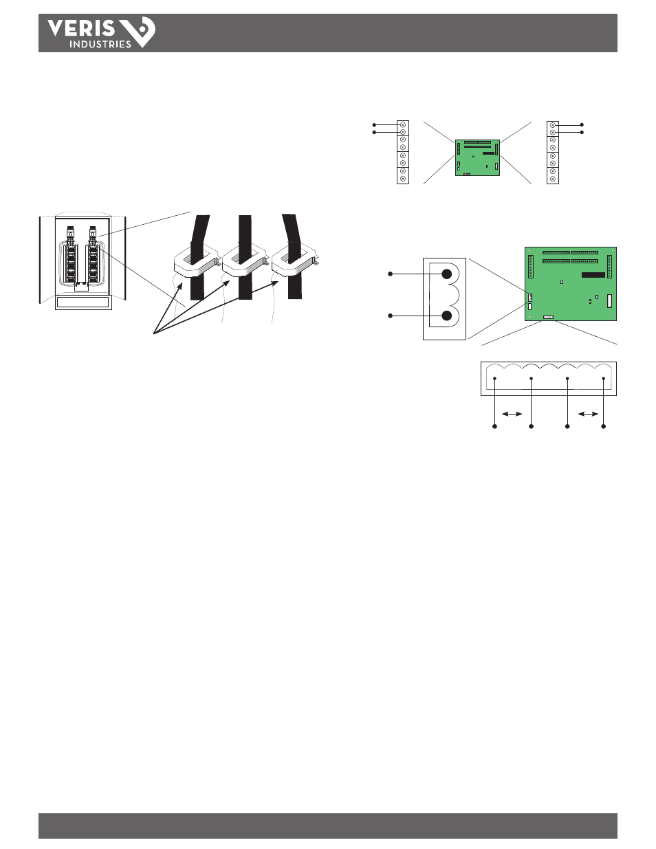
Figure 9
V1 V2 V3 N
V2/N
V1
90-277 VAC
L - L
L - N
Line to Line (L-L) Voltage: 150 to 480 VAC
Line to Neutral (L-N) voltage: 90 to 277 VAC
Voltage taps are shared by both panels.
Figure 7
Figure 8
Set up Modbus registers 115-118 for CT scaling.
Use base + 1 address for Panel 2 setup.
I1
I2
I3
IN
I1
I2
I3
IN
±
±
±
±
±
±
±
±
Panel 2
Panel 1
CT Input
(0-0.333 VAC)
CT Input
(0-0.333 VAC)
E30 CURRENT SENSOR STRIP
E30 CURRENT SENSOR STRIP
E30 CURRENT SENSOR STRIP
E30 CURRENT SENSOR STRIP
Panel 1
Panel 2
Recommended CT:
Veris Industries H6810, H6811, H6812 Series with 0.333VAC output.
Available in 100A max. to 2400A max.
Call a Veris sales rep if higher amperages are required.
8. Wire RS-485 communications (see diagrams in Wiring section).
9. Connect 0.333VAC CTs to the main conductors by snapping CTs around lines,
observing local codes regarding bending radius (optional; Figure 8).
10. Connect 2-wire 90-277VAC power to main power terminals. Observe polarity. For
the E30A and E30B, connect voltage lines to the voltage taps (Figure 8). Equip
voltage lines with fuses.