Commissioning guide – Veris Industries E3X Commissioning Guide User Manual
Page 9
PAGE 9
©2011 Veris Industries USA 800.354.8556 or +1.503.598.4564 / [email protected]
03112
Alta Labs, Enercept, Enspector, Hawkeye, Trustat, Veris, and the Veris ‘V’ logo are trademarks or registered trademarks of Veris Industries, L.L.C. in the USA and/or other countries.
TM
COMMISSIONING GUIDE
E3x
There are two types of alarms, Latching and Non-Latching.
Latching Alarm Settings Defined
High-High Alarm Delay (s): Number of seconds the current in a circuit needs to be continuously above the High-High Alarm Threshold before the High-High alarm is
activated (default = 10 s).
High Alarm Delay (s): Number of seconds the current in a circuit needs to be continuously above the High Alarm Threshold before the High alarm is activated (default =
10 s).
Low Alarm Delay (s): Number of seconds the current in a circuit needs to be continuously below the Low Alarm Threshold before the Low alarm is activated (default =
10 s).
Low-Low Alarm Delay (s): Number of seconds the current in a circuit needs to be continuously below the Low-Low Alarm Threshold before the Low-Low alarm is
activated (default = 10 s).
Latching Alarm On Time (s): Number of seconds the current in a circuit needs to stay above the low-low alarm threshold level before the latching alarms are armed/
enabled for that channel (default = 10 s).
Latching Alarm Off Time (s): Number of seconds the current in a circuit needs to be below the Low-Low Alarm Threshold level before the latching alarm is de-activated
(default = 30 s). After this point, on this channel, all latching alarms are disabled.
High-High Alarm Threshold (%): Limit for the High-High current alarm state, expressed as a percentage of the breaker size (default = 70%). For example, the High-
High alarm threshold for a 20 A breaker is 14 A (i.e., 20 x 0.70). To disable this alarm (for all channels) set its threshold value to 0%.
High Alarm Threshold (%): Limit for the High current alarm state, expressed as a percentage of the breaker size (default = 60%). For example, the High alarm threshold
for a 20 A breaker is 12 A (i.e., 20 x 0.60). To disable this alarm (for all channels) set its threshold value to 0%.
Low Alarm Threshold (%): Limit for the Low current alarm state, expressed as a percentage of the breaker size (default = 7.5%). For example, the Low alarm threshold
for a 20 A breaker is 1.5 A (i.e., 20 x 0.075). To disable this alarm (for all channels) set its threshold value to 0%.
Low-Low Alarm Threshold (%): Limit for the Low-Low current alarm state, expressed as a percentage of the breaker size (default = 2.5%). For example, the Low-Low
alarm threshold for a 20 A breaker is 0.5 A (i.e., 20 x 0.025). To disable this alarm (for all channels) set its threshold value to 0%.
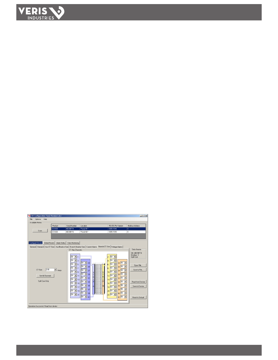
7. Branch CT Size.
Set the size of each CT monitoring the branch circuit breakers. For the E30 solid-core products, the CT size for each branch circuit is automatically set and locked at 100
Amps. For the E31 split-core products, select the appropriate CT size per channel from the drop down menu. If all channels must be set to the same CT size, the Set All
Channels button can be used for convenience.