Commissioning guide, Sub-interval kw – Veris Industries E3X Commissioning Guide User Manual
Page 6
PAGE 6
©2011 Veris Industries USA 800.354.8556 or +1.503.598.4564 / [email protected]
03112
Alta Labs, Enercept, Enspector, Hawkeye, Trustat, Veris, and the Veris ‘V’ logo are trademarks or registered trademarks of Veris Industries, L.L.C. in the USA and/or other countries.
TM
COMMISSIONING GUIDE
E3x
These settings apply to current demand (registers 269-272, 1462 - 1503) and power demand (registers 277, 1378-1419).
Configure the number of sub intervals. The default is 1, but it can be set for 1-6 sub-interval windows.
Configure sub-interval length (register 72). The default is 900 sec (15 minutes), but it can be set from 10 – 32767 (in seconds). For Sync to Comms, set to 0. Sync to
Comms mode will start demand calculations based on writes to Modbus register 295 with a value of 26012 (decimal).
Calculate Demand by continuously summing the subinterval averages and dividing by the number of subintervals. The subinterval average is recalculated every second
from the RMS values for current and power. The Demand register will update at the end of each subinterval. See the example below. For Block mode, set the number of
subintervals to 1 (Reg 71).
Sub-Interval
kW
15
10
5
1
4
3
2
5
6
10
8
7
5
3
15
Sub-Interval Length
(user configurable)
Demand is updated
between each
sub-interval
subinterval average (N) (kW)
Demand =
6
Σ
n = 1
6
8 kW = 6 6 6 6 6
6
10
8
7
5
3
15
+
+
+
+
+
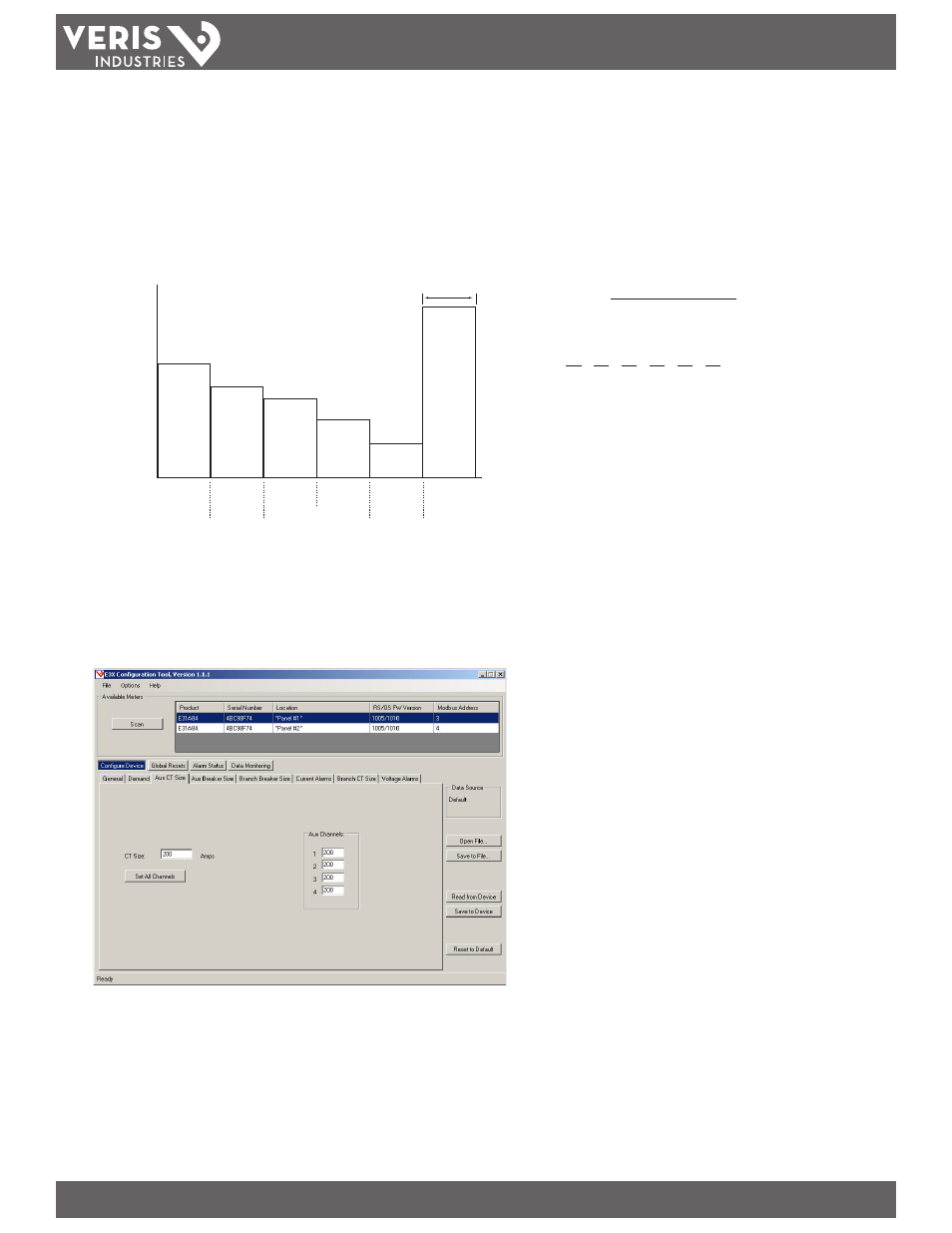
3. Aux CT Size.
Set the CT size for each channel. Enter the value for each channel separately, or enter one value and click Set All Channels. Auxiliary #1 (register 115) to Auxiliary #4
(register 118) define the auxiliary or “mains” CT size (typically 200 A). Type the appropriate numeric value for each auxiliary CT installed in the panel. CT size must be
1-32,767. Set this value for each panel on the E3x.