Commissioning guide, Latching alarm examples – Veris Industries E3X Commissioning Guide User Manual
Page 17
PAGE 17
©2011 Veris Industries USA 800.354.8556 or +1.503.598.4564 / [email protected]
03112
Alta Labs, Enercept, Enspector, Hawkeye, Trustat, Veris, and the Veris ‘V’ logo are trademarks or registered trademarks of Veris Industries, L.L.C. in the USA and/or other countries.
TM
COMMISSIONING GUIDE
E3x
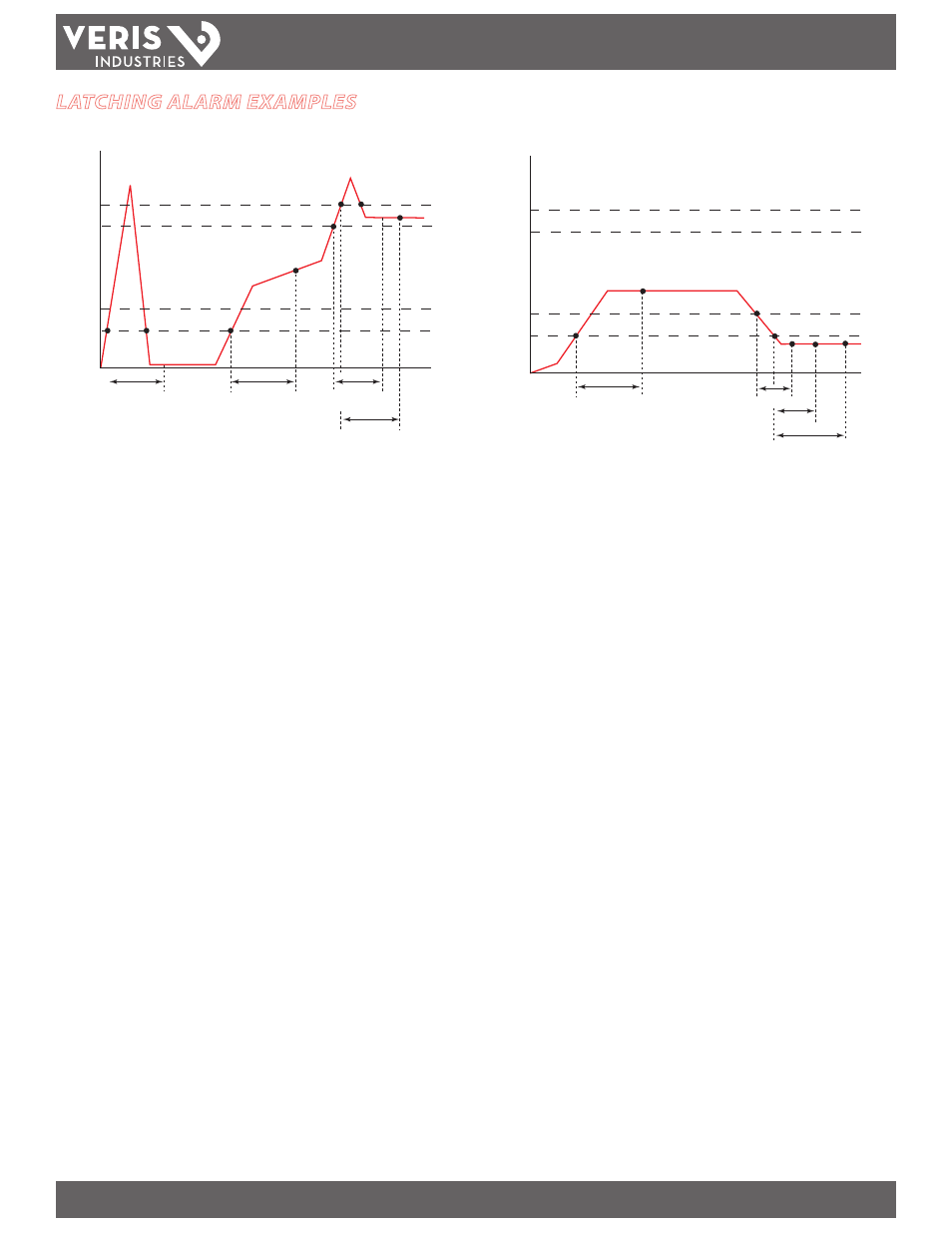
LATCHING ALARM EXAMPLES
Example 1
1. Current rises above LL (low-low alarm threshold) — this starts the Latching Alarm
ON timer.
2. Current drops below LL before the Latching Alarm ON time period ends, so
alarming is not enabled. The Latching Alarm ON timer is reset.
3. Current rises above LL — this starts the Latching Alarm ON timer.
4. Current remains above the low-low alarm threshold, beyond the time period
specified by the Latching Alarm ON time setting — this enables the Latching
Alarm (all Latching Alarms for the specific channel are armed).
5. Current rises above H (high alarm threshold) — this starts the high alarm delay
timer.
6. Current rises above HH (high-high alarm threshold) — this starts the high-high
alarm delay timer.
7. Current drops below HH before the high-high alarm delay period ends, so the
high-high alarm delay timer is reset.
8. High alarm is latched at the end of the high alarm delay time period.
Time
HH
H
Amps
L
LL
Latching
alarm ON time
Latching Alarm
OFF Time
L delay
1
3
4
5 6
7
14
12
1.5
0.5
2
LL delay
Time
HH
H
Amps
L
LL
Latching
alarm ON time
Latching
alarm ON time
High-High
alarm delay
High
alarm delay
1
2
3
4
5
6
7
8
14
12
1.5
0.5
Example 2
1. Current rises above LL (low-low alarm threshold) — this starts the Latching Alarm
ON timer.
2. Current remains above the low-low alarm threshold, beyond the time period
specified by the Latching Alarm ON time setting — this enables the Latching
Alarms (all Latching Alarms are armed).
3. Current drops below L (low alarm threshold) — this starts the low alarm delay
timer.
4. Current drops below LL (low-low alarm threshold) — this starts the low-low
alarm delay timer and the Latching Alarm Delay timer.
Note: When the circuit current is continuously below the Low-Low Alarm
Threshold (%) setting for the duration of the Latching Alarm OFF time period
(and longer), the latching alarms for that channel are disarmed. At this point,
the latched alarming feature is disabled (i.e. alarms disarmed), even though
the Low, Low-Low and Latching Alarms are latched.
5. Low alarm is latched at the end of the L delay (low alarm delay) time period.
6. Low-low alarm is latched at the end of the L-L delay (low-low alarm delay) time
period.
7. Current remains below the low-low alarm threshold, beyond the time period
specified in the Latching Alarm OFF time setting, thus setting the Latching Alarm
Off register for that channel