Commissioning guide – Veris Industries E3X Commissioning Guide User Manual
Page 10
PAGE 10
©2011 Veris Industries USA 800.354.8556 or +1.503.598.4564 / [email protected]
03112
Alta Labs, Enercept, Enspector, Hawkeye, Trustat, Veris, and the Veris ‘V’ logo are trademarks or registered trademarks of Veris Industries, L.L.C. in the USA and/or other countries.
TM
COMMISSIONING GUIDE
E3x
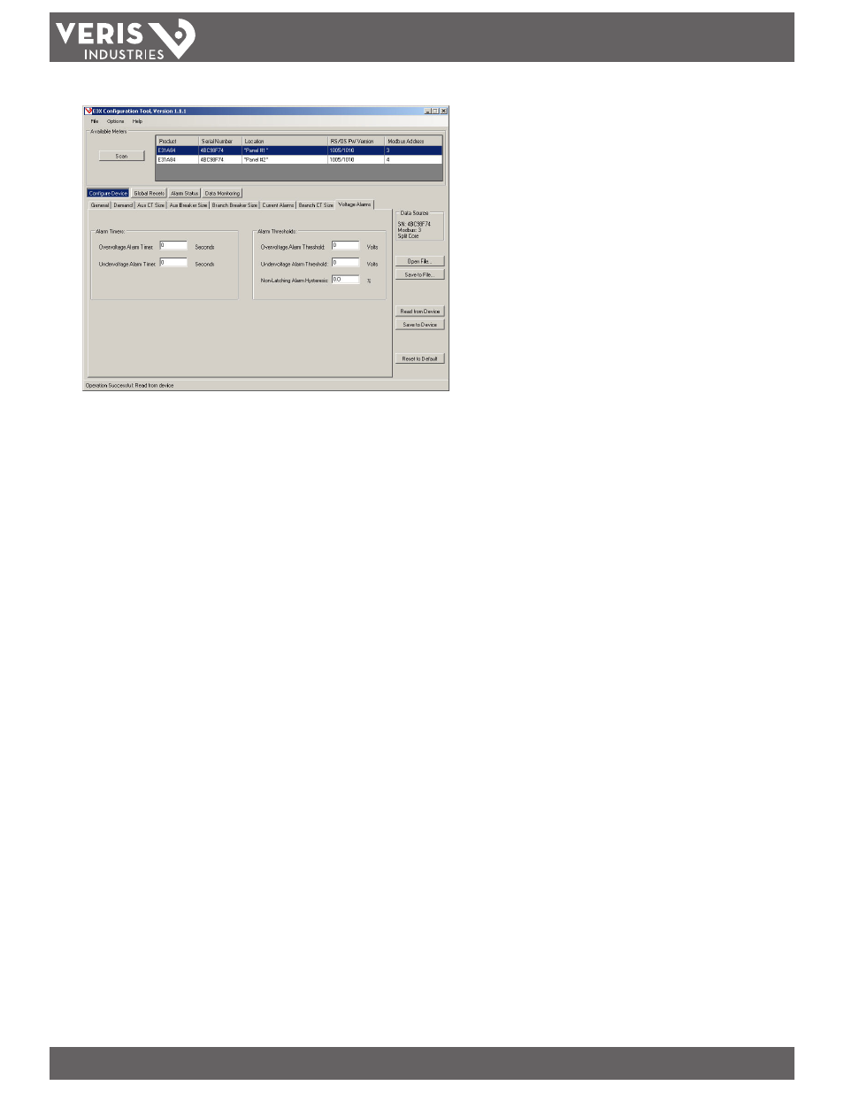
8. Voltage Alarms.
Line-to-Line Voltage Alarms Defined
The Voltage Alarm setup parameters define the alarm delay (timer) and threshold (limit) for the voltage inputs monitored by the E3x (E3x model A & B Only). Voltage
alarms are global; settings and alarms are shared between both panels for main boards with four ribbon cable connections.
The alarm timer settings define the length of time that a voltage input must be in an alarm state (i.e. exceeds the overvoltage alarm threshold or falls below the
undervoltage alarm threshold) before activating the latching alarm. A return to normal (non-alarm) state is instantaneous, so the alarm timer is reset if the voltage
returns to the normal state before the timer expires. The voltage alarms are always enabled unless the threshold is set to zero, unlike the current alarms there is no
On-Time Delay.
The latching and non-latching voltage alarms share overvoltage and undervoltage thresholds.
The non-latching voltage alarm is set as soon as the voltage inputs are in an alarm state (i.e. exceeds the overvoltage alarm threshold or falls below the undervoltage
alarm threshold) and are cleared as soon as the voltage inputs are out of an alarm state plus the hysteresis setting (i.e. below the overvoltage alarm threshold minus
hysteresis or exceeds the undervoltage alarm threshold plus hysteresis).
Overvoltage Alarm Timer: Enter the number of seconds the voltage can exceed Over Voltage Threshold level before activating the Over Voltage Latching alarm.
Undervoltage Alarm Timer: Enter the number of seconds the voltage can drop below the Under Voltage Threshold level before activating the Under Voltage Latching
alarm.
Overvoltage Alarm Threshold (V): Type the limit for the Over Voltage alarm state in Volts. To disable this alarm (for all voltage inputs) set its threshold value to 0 Volts.
Threshold for both Latching and Non-Latching alarm.
Undervoltage Alarm Threshold (V): Type the limit for the Under Voltage alarm state in Volts. To disable this alarm (for all voltage inputs) set its threshold value to 0
Volts. Threshold for both Latching and Non-Latching alarm.
Non-Latching Alarm Hysteresis (%): Type the value, expressed as a percentage of the alarm threshold, that defines how much the voltage must fall below the Over
voltage threshold or rise above the Under voltage threshold to determine the alarm’s “OFF” state.