A. making connections to the indicator, A.1 load cell connections – Ohaus CKW WASHDOWN CHECKWEIGHING SCALES_INDICATOR Manual en User Manual
Page 57
CKW-55 CHECKWEIGHER
APPENDIX A
EN-53
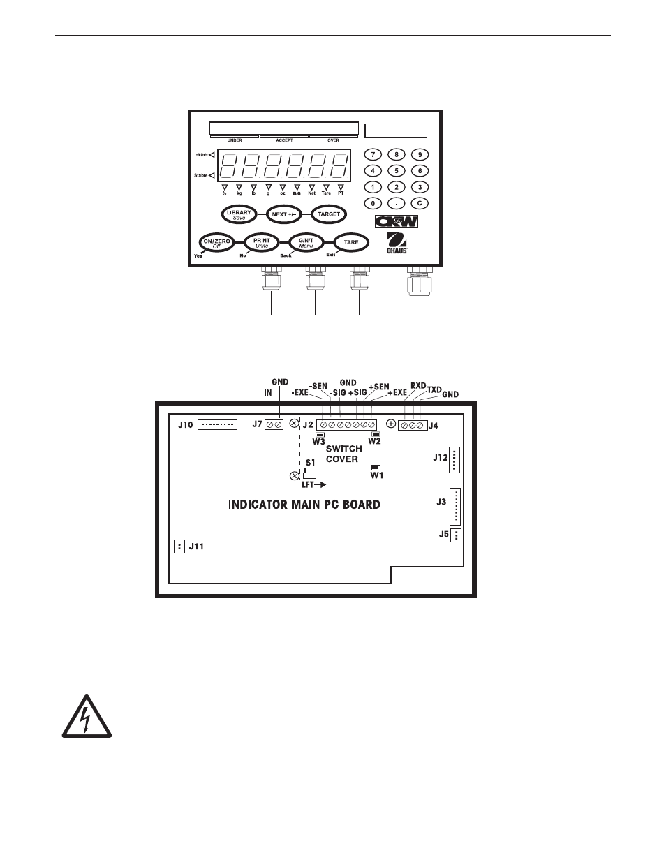
A. MAKING CONNECTIONS TO THE INDICATOR
The CKW-55 Indicator housing contains 4 liquid-tight connectors at the bottom for external cabling. Figure A-1 illustrates the
locations of the liquid tight connectors.
Figure A-1. Cable Entry Identification.
CAUTION: ELECTRICAL SHOCK HAZARD. REMOVE ALL POWER CONNECTIONS TO
THE INDICATOR BEFORE SERVICING OR MAKING INTERNAL CONNECTIONS.
THE HOUSING SHOULD ONLY BE OPENED BY AUTHORIZED AND QUALIFIED PERSONNEL,
SUCH AS AN ELECTRICAL TECHNICIAN.
Unfasten the four side screws of the indicator housing. Pull the front cover forward. Pass the load cell cable through the
liquid-tight connector at the bottom and center of the housing. Pass the cable through the large ferrite bead that is attached
to the internal plastic clip.
Figure A-2. Printed Circuit Board Connections.
..
..
..
I/O
LOAD
CELL
I/O
AC POWER
A.1 LOAD CELL CONNECTIONS
Figure A-2 illustrates the locations of the printed circuit board connections.
- MB45 MOISTURE ANALYZER Manual (70 pages)
- PRIMER BALANCE Manual (16 pages)
- DEFENDER 5000 BENCH SCALES Cable Adapter Kit Manual multi (2 pages)
- CARAT PLUS PRECISION JEWELRY BALANCES 2nd RS232 Serial Interface Kit Manual multi (24 pages)
- DEFENDER 5000 Semi-Washdown Scales Data Sheet (4 pages)
- SCOUT PRO PORTABLE BALANCES Data Sheet (4 pages)
- JR Series Electronic Balances (32 pages)
- EB COMPACT SCALES Data Sheet (2 pages)
- E1M110 Explorer Balances (47 pages)
- RANGER COUNT 3000 COMPACT COUNTING SCALES Data Sheet (4 pages)
- RANGER ADVANCED COMPACT COUNTING SCALES Manual en (72 pages)
- Valor 2000 COMPACT FOOD SCALES Data Sheet (4 pages)
- DEFENDER D500M MECHANICAL BENCH SCALE Data Sheet (2 pages)
- CKW BASE Manual multi (40 pages)
- Valor 3000 COMPACT FOOD SCALES Manual multi (104 pages)
- Valor 1000 COMPACT FOOD SCALES Data Sheet (2 pages)
- PAJ GOLD PLUS PRECISION JEWELRY BALANCES Data Sheet (4 pages)
- Voyager Balances (329 pages)
- SD COMPACT BENCH SCALES Data Sheet (2 pages)
- AS Series Electronic Balances (89 pages)
- CL PORTABLE BALANCES Manual multi (44 pages)
- CL PORTABLE BALANCES Data Sheet (2 pages)
- HH 120D HAND HELD SCALES Manual multi (40 pages)
- CD-11 Indicator Manual multi (120 pages)
- CARAT PLUS PRECISION JEWELRY BALANCES Manual en (56 pages)
- SCOUT PRO PORTABLE BALANCES Installation it (2 pages)
- DEFENDER 7000 BENCH SCALES Base Manual (2 pages)
- GT4100DG Electronic Balances (52 pages)
- FD Series STAINLESS STEEL COMPACT SCALES Manual multi (88 pages)
- PL150 Scale Bases (10 pages)
- DEFENDER 3000 BENCH SCALES Base Manual en (8 pages)
- DEFENDER 3000 Xtreme Data Sheet (2 pages)
- HJ2001 HARVARD JUNIOR MECHANICAL BALANCE Data Sheet (2 pages)
- VN Series Floor Scale Data Sheet (4 pages)
- DS Series Electronic Digital Bench Scales (38 pages)
- YA GOLD HAND HELD JEWELRY SCALES Data Sheet (2 pages)
- DEFENDER 7000XW Xtreme Square Washdown Scales Data Sheet (4 pages)
- DEFENDER 7000 Square Semi-Washdown Scales Data Sheet (4 pages)
- PS POCKET JEWELRY SCALES Data Sheet (2 pages)
- RANGER COMPACT HIGH RESOLUTION SCALES Data Sheet (2 pages)
- CARAT & GOLD LIGHT PORTABLE JEWELRY BALANCES Manual multi (88 pages)
- 311 CENT-O-GRAM BALANCE Manual (8 pages)
- DEFENDER 5000 Rectangular Scales Data Sheet (4 pages)
- MB301 Electronic Balances (29 pages)