Technical data functional diagram ba-c – M&C TechGroup BA-C Data sheet User Manual
Page 2
M&C TechGroup Germany GmbH • Rehhecke 79 • 40885 Ratingen • Germany
[email protected] • www.mc-techgroup.com • Fon +49 2102 935-0 • Fax +49 2102 935-111
12.2
Technical specifications and illustrations are without
obligation, subject to modifications. 09.96/01.07
AircleanupsupplyseriesBA
versionBA-C
Part No.
60A3000A
Flow (lpm)
max. 12
Instrument air inlet pressure (psig)
70 - 145
Ambient temperature
+41 °F to +104 °F
Start up time
approx. 5 min.
Air purity
Total hydrocarbon content < 0,1 ppm C
n
H
m
CO
2
- concentration
< 2 ppm
Dewpoint
< -100 °F
Catalyst poisons
Halogens, silicon, lead, materials containing phosphorous
Storage temperature
-13 °F to +149 °F
Relative humidity
<75 %, avoid condensation
Inlet gas connection
compressed air in G1/4"i
Outlet gas connections
G 1/4”i
Condensate connection
G1/4” i
Power supply
115V 60Hz 150W
Status signal contact for pressure and temperature
1 contact - potential free, contact rating 24V, 1A
Case protection
IP 20 EN60529
Wall mounting or 19”- housing dimensions (in)
6” x 19” x 10” (H x W x D)
Weight (lbs)
approx. 46
Electrical equipment standard
EN 61010
Technical data
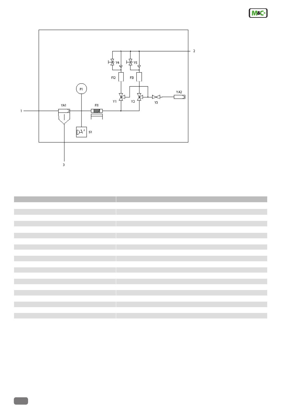
Functional diagram BA-C
1 Air inlet
2 Zero air outlet
3
Condensate outlet
FI1 Oxidizer
FI2 Mol sieve column
FI3 Mol sieve column
P1 Pressure gauge
S1 Pressure switch
Y1 Solenoid valve
Y2 Solenoid valve
Y3 Solenoid valve
Y4 Check/Needle valve
Y5 Check/Needle valve
YA1 Air filter with
condensate drainer
YA2 Sound absorber
Notes:
1) Exceeds 40 CFR 72.2, 40 CFR 75 Appendix H and the Acid Rain Program CEMS Field Audit Program Manual zero grade air material requirements.
2) Custom configuration and higher purity specification are available on request.