Dimensions, Drilling diagramm – M&C TechGroup L_PV-1 Series Data sheet User Manual
Page 2
M&C TechGroup Germany GmbH • Rehhecke 79 • 40885 Ratingen • Germany
[email protected] • www.mc-techgroup.com • Fon +49 2102 935-0 • Fax +49 2102 935-111
11.1
Technical specifications and illustrations are without
obligation, subject to modifications. 08.98/11.06
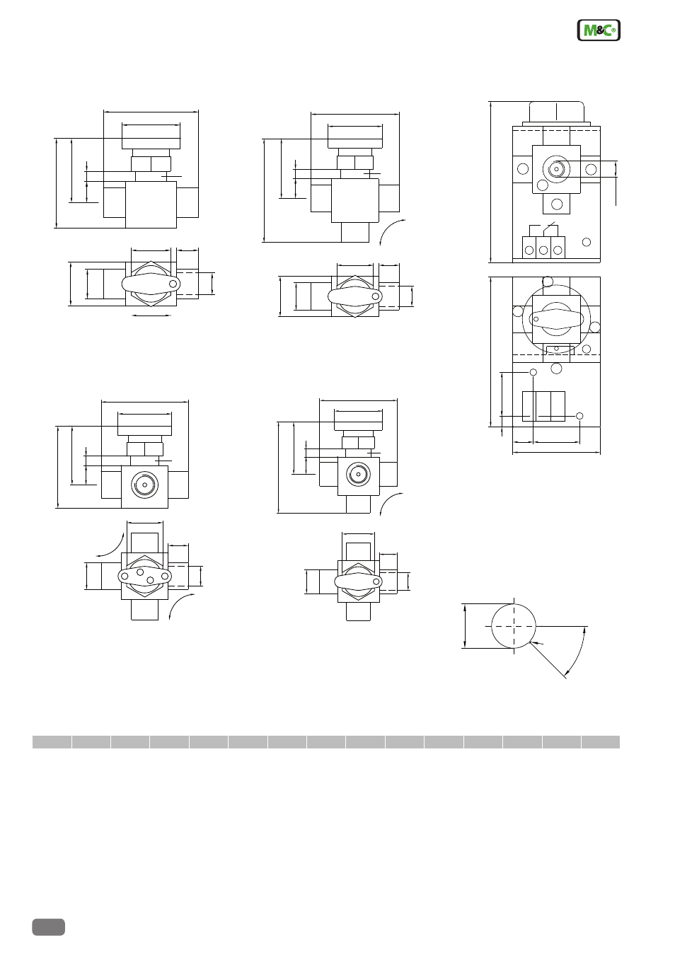
Dimensions
Abmessungen in mm
3-way-ball valve 3L/PV-1
2-way-ball valve 2L/PV-1
5-way-ball valve 5L/PV-1
4-way-ball valve 4L/PV-1
5-way-ball valve 5L/PV-1
with status contact
1.Central point/outlet
2. controlled connection,
i.e. sample gas
3. I.e. zero gas
4. I.e. calibration gas 1
5. I.e. calibration gas 2
Drilling diagramm
D
G
H
H1
I
L
L1
L2
L3
s
SW1
SW2
T
w1
w2
ø 20
G1/4"i
41,5
12,5
46
65
15
75
57,5
max. 5
32
27
32
26
22
D
T
G
SW1
L1
H
S
H1
L3
I
L
W1
D
T
G
L1
SW2
H
S
H1
L2
I
L
W2
G1/4"
64
34
15
32
8
110
120
2
5
4
3
5
2
3
1
3
2
1
ш 5
3
1 2
ш 5
D
G
L1
SW1
H
S
H1
L3
I
L
W1
D
G
L1
SW2
H S
H1
L2
I
L
W2
diameter 22
R0,75
45
*
plate thickness < 7 mm
* controlled position
drilling diagram
- SP10 Operator's manual (14 pages)
- N9 KP18 Operator's manual (21 pages)
- SP2000_20SS 150 Data sheet (3 pages)
- SP3100 Data sheet (6 pages)
- PSP4000-H _C _T Data sheet (4 pages)
- SP2200-H_C_I_BB_F Data sheet (2 pages)
- SP35-H... for gas sample probe SP2000-H... Data sheet (2 pages)
- FP-BF Data sheet (2 pages)
- SP3200 Operator's manual (28 pages)
- FPF-0,1 Operator's manual (2 pages)
- PSS-10_1 Operator's manual (23 pages)
- CSS-V2 Data sheet (3 pages)
- PMA 50 EEX Operator's manual (48 pages)
- MP30 Operator's manual (18 pages)
- SP2600-H_C_I_BB_F_0,1GF190 Data sheet (3 pages)
- SR25.1_Ex Operator's manual (22 pages)
- PMA 10S Operator's manual (27 pages)
- CSS-M_W Data sheet (3 pages)
- PAS-500 Operator's manual (20 pages)
- SP2000H320_DIL... Data sheet (3 pages)
- SP3200 Data sheet (6 pages)
- FA-1_2_3,bi Operator's manual (24 pages)
- SR25 Data sheet (2 pages)
- SP3000 Data sheet (4 pages)
- PAS Series Data sheet (2 pages)
- CG Series Data sheet (2 pages)
- ECP 20-2 Data sheet (3 pages)
- MP30-EX Data sheet (2 pages)
- PSP4000-H_C_T Operator's manual (24 pages)
- DIL-U Data sheet (2 pages)
- ADS-So Data sheet (2 pages)
- VC-2-SL Operator's manual (18 pages)
- ECM-ExII Operator's manual (39 pages)
- MP12 Operator's manual (17 pages)
- FPF+ Data sheet (2 pages)
- KS 2.Ex Operator's manual (17 pages)
- PMA 50 EEX Data sheet (3 pages)
- PMA 10S Data sheet (3 pages)
- Gas Sample Probes Series SP Data sheet (2 pages)
- BA-C Operator's manual (16 pages)
- MV3_2-H Series Operator's manual (18 pages)
- VC-2-SL Data sheet (3 pages)
- FM-200K-H_FA Operator's manual (16 pages)
- SP 30-H.._EX2 Operator's manual (16 pages)
- SP2006-H280_DIL Operator's manual (35 pages)