Application example for ecm-1, Dimensions – M&C TechGroup ECM-EX2-2 Data sheet User Manual
Page 2
M&C TechGroup Germany GmbH • Rehhecke 79 • 40885 Ratingen • Germany
[email protected] • www.mc-techgroup.com • Fon +49 2102 935-0 • Fax +49 2102 935-111
6.3
Technical specifications and illustrations are without
obligation, subject to modifications. 10.99/06.06
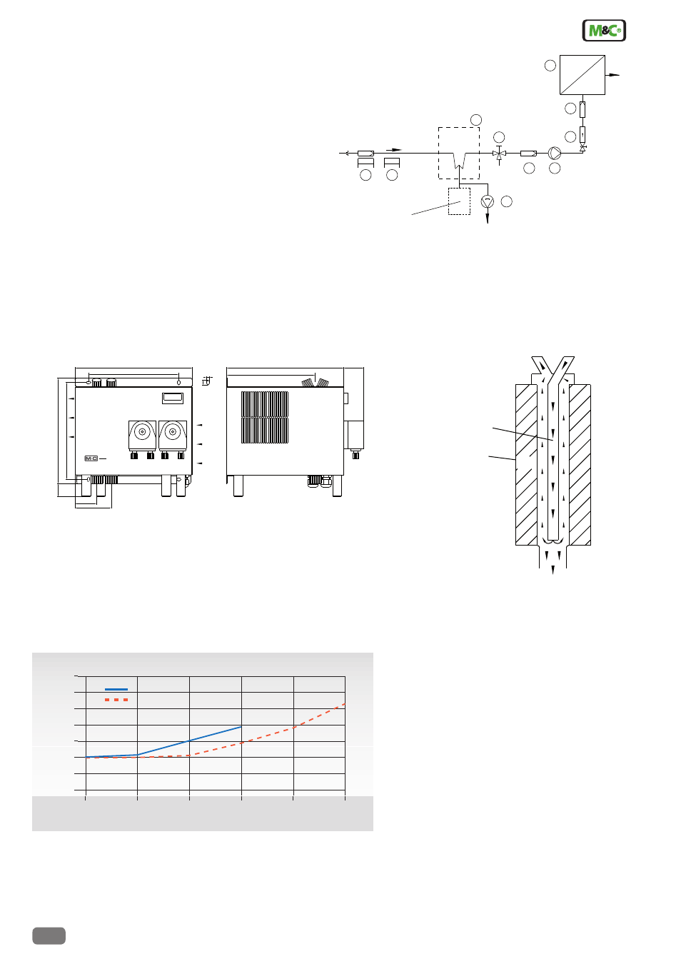
Dimensions in mm
Drawing shows ECM-2G with two heat exchanger out of glass.
Heat exchanger(s) and peristaltic pump(s) to be ordered optionally!
Functioning diagram of M&C
Jet-Stream heat exchanger
Sample gas outlet dew point stability at gas inlet dew point of 60 °C.
Characteristics of heat exchanger out of PVDF or stainless steel on request.
Compact gas cooler ECM-1 / ECM-2 / ECM-EX2-1 / ECM-EX2-2
Sample gas outlet dew point stability
220
240
30
50
84
11
6
46
204
270
208
270
Vent from the
compressor
ventilation
opening
Cooler
ECM
M&C Jet-Stream
heat exchanger
Cooling block
Condensate - OUT
Sample gas - IN
Sample gas - OUT
+5°C
Application example for ECM-1
1
Heated filter sample probe SP210-H or SP2000-H
2
Heated sample line 4M4/6
3
Cooler ECM-1G
4
3-way ball valve 3L/PV-1
5
Peristaltic pump SR25.2
6
Diaphragm pump MP47 or MP06/12 or N5KP
7
Fine filter FP-2T-D with liquid alarm LA1
8
Aerosol filter CLF-5 /W optional according to application
9
Flow meter FM10 or FM40, 25-250 Nl/hr
10 Analysers f. e. PMA100
8
Alternative:
trap with float or condensate
collection vessel
5
condensate OUT
+5°C
4
3
10
9
7
ECM-1
1
2
sample gas IN
test gas
IN
6
Dimensions
Sample flow rate Nl/hr
Sa
m
pl
e
ou
tle
t d
ew
p
oi
nt
°
C
0
50
100
150
200
250
3
4
5
6
7
8
9
10
ECM-2G
ECM-1G