Pneumatic connexions, Figure 2, Connexions sp2200-h/c/i/bb and sp2200-h/c/i/bb/f – M&C TechGroup SP2200-H_C_I_BB_F Operator's manual User Manual
Page 14: 1 pneumatic connexions
14
Gas sampling and gas conditioning technology
2-1.1.6-ME
Now insert the process-internal probe section of the complete probe unit into the probe con-
nection, but first attach the flange seal to the probe connection and screw using the screws
and nuts supplied.
N O T E !
A preferred mounting position is to have the probe with its sample gas out-
let pointing downwards, although this is not absolutely necessary for per-
fect functioning. An advantage as well is mounting the probe with an angle
(10°) downwards.
12.1
PNEUMATIC CONNEXIONS
Remove the upper part of the sample line's mounting bracket and insert the sample line
through the silicon lid into the threaded pipe joint and connect it.
The temperature-resistant, stainless steel connectors supplied by M&C have a double ferrule
system to ensure reliable sealing. After tightening the nuts of these connectors by hand, they
should then be tightened exactly 1¼ of a turn using a flat spanner and are then properly
mounted.
If a PTFE tube is used as sample line, an insert must under all circumstances be inserted in
the end of the tube in order to prevent the tube being pressed together.
Screw on the upper part of the mounting bracket.
In the case of larger sample line diameters, it may be necessary for the central mounting of
the sample line to loosen the two screws and move the small mounting bracket of the mount-
ing bracket and then re-tighten them. Now place the heat conducting jaws around the sample
gas connection in the retaining slot and fix with the knurled nuts.
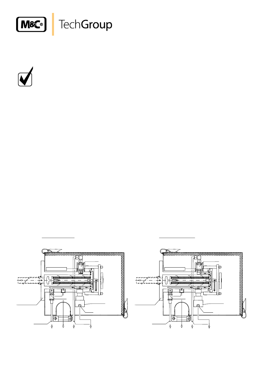
If the probe has a check valve /R for calibration gas feeding or backflush, the corresponding
pipe should be connected to the 6mm piping connection.
If the probe is fitted with an inlet ball valve with pneumatic drive, the control line for operating
the pneumatic controller element is to connected at the 1/8"-NPT connecting thread.
For safety reasons, the ball valve is to be closed before mounting the probe.
Now replace the protection shield and fasten using the pressure clamps.
(
P
3-10bar)
1/4"NP
T
(
P
>0,7bar)
1/8"NP
T
1/8"NP
T
(
P
3-10bar)
(
P
>0,7bar)
1/4"NP
T
SP2200-H/C/I/BB/F
Check valve
Isolation valve
Check valve
T
ube DN6/8
Blow back in
Sample out
Flange DN65 PN6
T
ube DN4/6
Cal.-gas in
Control in
Check valve
SP2200-H/C/I/BB
Control in
Sample out
T
ube DN6/8
Blow back in
Isolation valve
Flange DN65 PN6
Cal.-gas in
T
ube DN4/6
Check valve
Figure 2 Connexions SP2200-H/C/I/BB and SP2200-H/C/I/BB/F