Supply connections, Connecting the heated sample line, Figure 1 – M&C TechGroup PSP4000-H_C_T Operator's manual User Manual
Page 12: Connection of the heated sample line
12
Gas sampling and gas conditioning technology
2-2.1-ME
The existing operational parameters are to be checked accordingly prior to commencing mounting
work.
Under / over pressure situation
mbar
bar
Process temperature
°C,
Min.
°C,
Max.
Dust loading
g/m³
Dust composition - grain size
µm
Gas composition
corrosive
toxic
explosive
Which parameters should be
measured, e.g. O
2
, CO, SO
2
, NOX,....,
Vol.%
mg/Nm³
ppm
Required amount of gas
l/h,
Min.
l/h,
Max.
Necessary T
90
time
sec.
14
SUPPLY CONNECTIONS
14.1 CONNECTING THE HEATED SAMPLE LINE
Remove the aluminium heat-conducting jaws at the probe's filter head by loosening the 4
screws from the gas outlet's threaded connection. The outlet's threaded connection is provided
for the connection of a tube with an external diameter of 6 mm (optionally 8 mm).
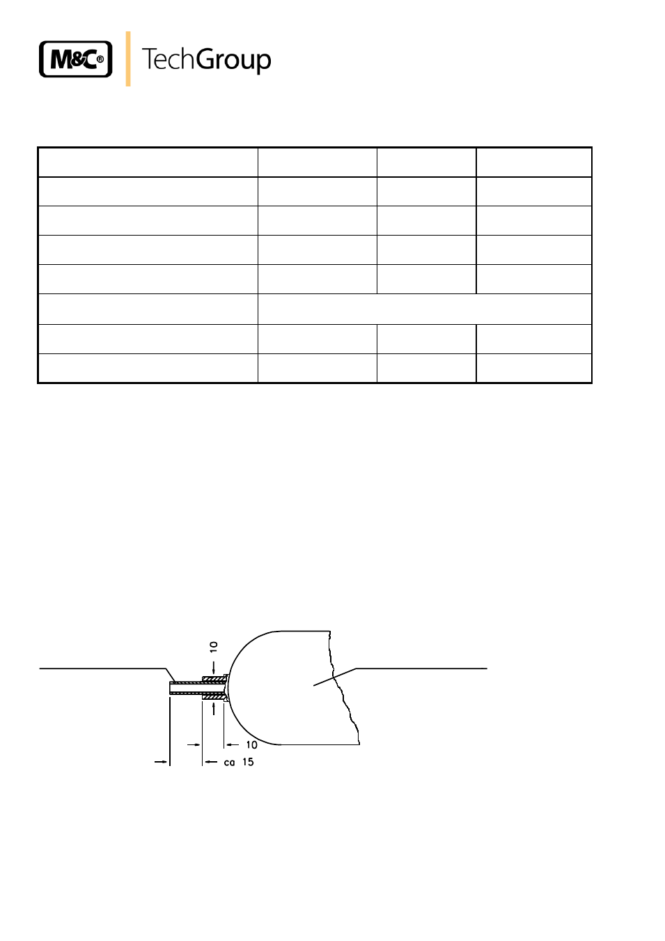
Before connecting a sample line not specified by M&C, the tube connection should be
prepared according to the following sketch.
M&C's heated sample lines type PSP 4M4/6 and PSP-W4M4/6 are manufactured to fit the
mechanical and electrical connections to the PSP4000-H... gas sample probe and already contain an
internal line for the probe's power supply.
Figure 1
Connection of the heated sample line
Push the insert into the PTFE tube in order to avoid the tube being compressed and slide the
red silicon protective ring up to the end of the heated sampling tube.
Introduce the PTFE tube into the threaded connection joint with the double-cutting ring system
to ensure sealing.
Heated sample line
PTFE-tube DN 4/6