Electronic controller fa-1.4, Figure 3, Electrical connection and dimensions fa-1.4 – M&C TechGroup FA-1_2_3,bi Operator's manual User Manual
Page 13
13
Gas sampling and conditioning technology
5-6.10-ME
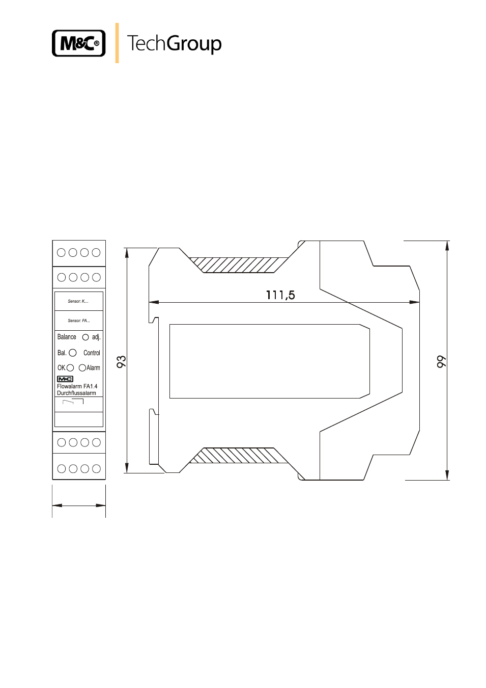
13.2 ELECTRONIC CONTROLLER FA-1.4
For the electrical connection, the following steps have to be carried out (see also figure 3):
The electrical connection of the sensors FA-1/2/3bi is to be made on the terminals 5 = yellow,
6 = green, 7m = white and 8 = brown.
The electrical connection of sensor KS 2 and the pre-amplifier K-FA.. is to be made on the
terminals 15 = yellow, 16 = green, 17 = white and 18 = brown.
The voltage supply happens on the terminals 1 = L, 2 = N and 4 = PE.
The alarm is to be connected to terminals 11 (MC), 12 (NC) and 14 (NO). In case of alarm
contact 11 and 12 are closed and voltage free.
For a mono-stable evaluation, the attached jumper must be mounted between the terminals 16
and 17 (this is not necessary for operation with pre-amplifier K-FA.. because a bi-stable or
mono-stable operation is set on the pre-amplifier (see chapter 13.3))
Figure 3
Electrical connection and dimensions FA-1.4
5 6 7 8
15 16 17 18
L/+ N/- PE PE
11 12 14 NC
1 2 3 4
ye. gn. wh. bn.
ye. gn. wh. bn.
22,5