Example application for ecp 20-2, Functioning diagram of m&c- heat exchanger – M&C TechGroup ECP 20-2 Data sheet User Manual
Page 2
M&C TechGroup Germany GmbH • Rehhecke 79 • 40885 Ratingen • Germany
[email protected] • www.mc-techgroup.com • Fon +49 2102 935-0 • Fax +49 2102 935-111
6.2
Technical specifications and illustrations are without
obligation, subject to modifications. 05.97/06.06
38
72
226
PG 9
PG 11
C
ON
C
385
280
60
90
95
210
Alarm contact
Power -in
ø7
GL 25
2xGL 18
Dimensions in mm
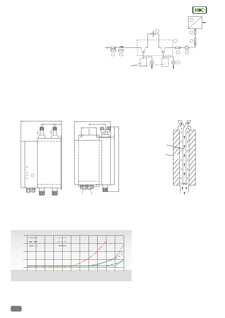
Example application for ECP 20-2
1 Heated filter sample probe SP2000-H
2 Heated sample line 4M4/6
3 Cooler ECP20-2
4 3-way ball valves 3L/PV-1
5 Peristaltic pumps SR25.1
6 Diaphragm pump MP47
7 Fine filter FP-2T-D with liquid alarm LA1
8 Aerosol filter CLF-5/W optional according to application
9 Flow meter FM10, 50-500 Nl/hr
10 Analyser, e. g. PMA1000
Alternative:
Trap with float or
condensate vessel
5
Condensate OUT
+5°C
4
3
10
9
8
7
ECP20-2
1
2
Sample Gass IN
Testgas
IN
6
Dimensions
ECP 20-2
Sample outlet dew point differ-
ence
for the gas cooler ECP20-2 with heat exchangers out of:
1
Glass
2
PVDF
3
Stainless steel 316Ti
in dependence on the gas flow rate and
40 °C and 60 °C sample inlet dew point
at 25 °C ambient temperature.
Functioning diagram of M&C-
heat exchanger
M&C Jet-Stream
heat exchanger
Cooling block
Condensate - OUT
Sample gas - IN
Sample gas - OUT
+5°C
Sample gas flow rate Nl/hr
S
am
pl
e
ou
tle
t d
ew
p
oi
nt
°
C
0
50
100
150
200
250
300
350
400
450
500
4
550
8
12
16
20
40 °C -2
60 °C -3
40 °C -3
60 °C -1
40 °C -1
60 °C -2
side view
front view