M&C TechGroup MP30 Operator's manual User Manual
Page 15
15
Gas sampling and gas conditioning technology
6-1.3.5-ME
14.1
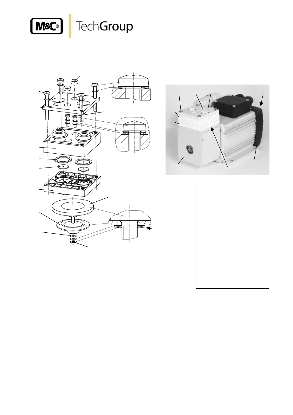
REPLACING DIAPHRAGMS, VALVE PLATES AND SEALING RINGS
Figure 4 shows a sectional drawing of the pump head.
1
2
3
4
5
6
7
8
9
10
11
15
Positioning
the cup
spring 11
Figure 3
Section drawing of pump head MP30
Replacing the diaphragm:
Mark position of pressure plate 15, head cover 4, intermediate plate 1 and housing 14 by making a
continuous line with a felt-tip pen.
Loosen four head screws 5.
Remove pressure plate 15, head cover 4 and intermediate plate 1 from pump housing.
Loosen four fixing screws in impeller cover 13 and remove.
Bring diaphragm 8 into top position by turning impeller 12;
Unscrew diaphragm on side edges anticlockwise.
1 Intermediate plate
2 Valve plate
3 Sealing ring
4 Head cover
5 Screw
6 Screw cap
7 Screw
8 Diaphragm
9 Supporting cup
10 Adjusting washers
11 Cup spring
12 Impeller
13 Impeller cover
14 Housing
15 Pressure plate
M Mark
15
14
13
12
1
4
5
6
M
- SP10 Operator's manual (14 pages)
- N9 KP18 Operator's manual (21 pages)
- SP2000_20SS 150 Data sheet (3 pages)
- SP3100 Data sheet (6 pages)
- PSP4000-H _C _T Data sheet (4 pages)
- SP2200-H_C_I_BB_F Data sheet (2 pages)
- SP35-H... for gas sample probe SP2000-H... Data sheet (2 pages)
- FP-BF Data sheet (2 pages)
- SP3200 Operator's manual (28 pages)
- FPF-0,1 Operator's manual (2 pages)
- PSS-10_1 Operator's manual (23 pages)
- CSS-V2 Data sheet (3 pages)
- PMA 50 EEX Operator's manual (48 pages)
- SP2600-H_C_I_BB_F_0,1GF190 Data sheet (3 pages)
- SR25.1_Ex Operator's manual (22 pages)
- PMA 10S Operator's manual (27 pages)
- CSS-M_W Data sheet (3 pages)
- PAS-500 Operator's manual (20 pages)
- SP2000H320_DIL... Data sheet (3 pages)
- SP3200 Data sheet (6 pages)
- FA-1_2_3,bi Operator's manual (24 pages)
- SR25 Data sheet (2 pages)
- SP3000 Data sheet (4 pages)
- PAS Series Data sheet (2 pages)
- CG Series Data sheet (2 pages)
- ECP 20-2 Data sheet (3 pages)
- MP30-EX Data sheet (2 pages)
- PSP4000-H_C_T Operator's manual (24 pages)
- DIL-U Data sheet (2 pages)
- ADS-So Data sheet (2 pages)
- VC-2-SL Operator's manual (18 pages)
- ECM-ExII Operator's manual (39 pages)
- MP12 Operator's manual (17 pages)
- FPF+ Data sheet (2 pages)
- KS 2.Ex Operator's manual (17 pages)
- PMA 50 EEX Data sheet (3 pages)
- PMA 10S Data sheet (3 pages)
- Gas Sample Probes Series SP Data sheet (2 pages)
- BA-C Operator's manual (16 pages)
- MV3_2-H Series Operator's manual (18 pages)
- VC-2-SL Data sheet (3 pages)
- FM-200K-H_FA Operator's manual (16 pages)
- SP 30-H.._EX2 Operator's manual (16 pages)
- SP2006-H280_DIL Operator's manual (35 pages)