Available slsm 3x configurations – EVS XT2 Version 11.01 - November 2012 Configuration Manual User Manual
Page 83
IN6/OUT1
IN5/OUT2
IN4/OUT3
IN3/OUT4
IN2/OUT5
IN1/OUT6
#REC
SLSM
2x
#REC
#PLAY
Prim.
Link
Sec.
Link
Prim.
Link
Sec.
Link
Prim.
Link
Sec.
Link
Prim.
Link
Sec.
Link
Prim.
Link
Sec.
Link
Prim.
Link
Sec.
Link
1
0
1
PLAY
1A
PLAY
1B
REC
1,2A
REC
1,2B
REC
1,1A
REC
1,1B
1
1
1
PLAY
1A
PLAY
1B
REC
2A
REC
2B
REC
1,2A
REC
1,2B
REC
1,1A
REC
1,1B
1
0
2
PLAY
1A
PLAY
1B
PLAY
2A
PLAY
2B
REC
1,2A
REC
1,2B
REC
1,1A
REC
1,1B
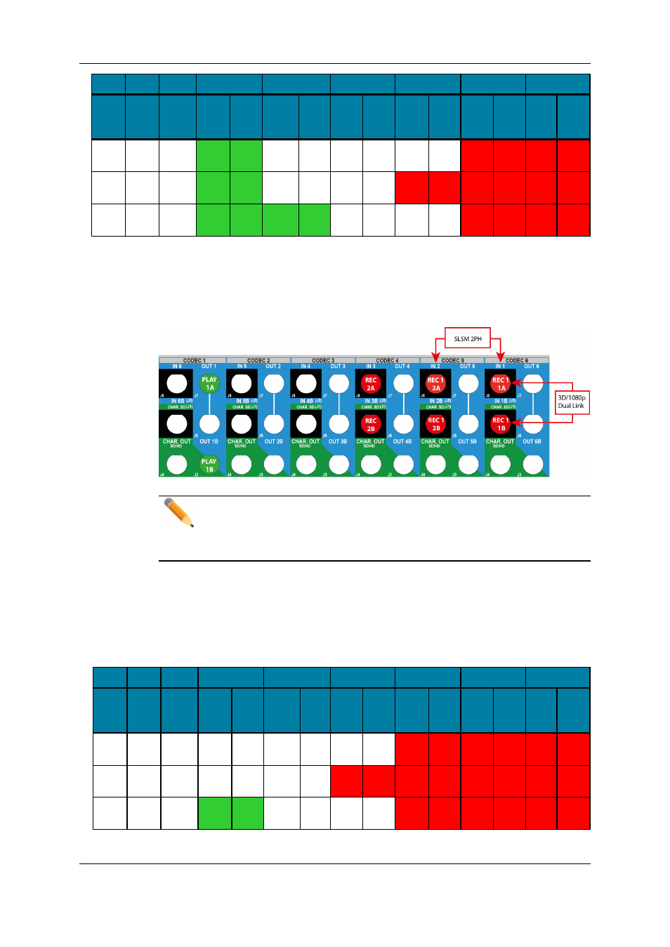
Example: 3D/1080p Dual Link 1SLSM 2x + 1REC+ 1PLAY
The BNC connectors to be used as record and play channels in a 3D or 1080p Dual Link
configuration 1SLSM 2PH + 1REC + 1 PLAY need to be cabled as shown below:
Note
In an equivalent configuration with a 3G interface, only the J8 connectors are
cabled. However the primary and secondary links on the codec module of the
V3X board are both used.
Available SLSM 3x Configurations
The tables below show the available 3D and 1080p configurations with SLSM 3 Phase
cameras on a XT2+ 6U server. They show the link assignment at the level of the codec
module of a V3X board.
IN6/OUT1
IN5/OUT2
IN4/OUT3
IN3/OUT4
IN2/OUT5
IN1/OUT6
#REC
SLSM
3x
#REC
#PLAY
Prim.
Link
Sec.
Link
Prim.
Link
Sec.
Link
Prim.
Link
Sec.
Link
Prim.
Link
Sec.
Link
Prim.
Link
Sec.
Link
Prim.
Link
Sec.
Link
1
0
0
REC
1,3A
REC
1,3B
REC
1,2A
REC
1,2B
REC
1,1A
REC
1,1B
1
1
0
REC
2A
REC
2B
REC
1,3A
REC
1,3B
REC
1,2A
REC
1,2B
REC
1,1A
REC
1,1B
1
0
1
PLAY
1A
PLAY
1B
REC
1,3A
REC
1,3B
REC
1,2A
REC
1,2B
REC
1,1A
REC
1,1B
73
3. Multicam Configuration
EVS Broadcast Equipment S.A. - November 2012
Issue 11.01.B