Engine & airframe systems – Garmin G1000 Socata TBM 850 User Manual
Page 109
190-00709-02 Rev. B
Garmin G1000 Pilot’s Guide for the Socata TBM 850
95
ENGINE & AIRFRAME SYSTEMS
SY
STEM
O
VER
VIEW
FLIGHT
INSTRUMENTS
EAS
AUDIO P
ANEL
& CNS
FLIGHT
MANA
GEMENT
HAZARD
AV
OID
ANCE
AFCS
ADDITIONAL
FEA
TURES
APPENDICES
INDEX
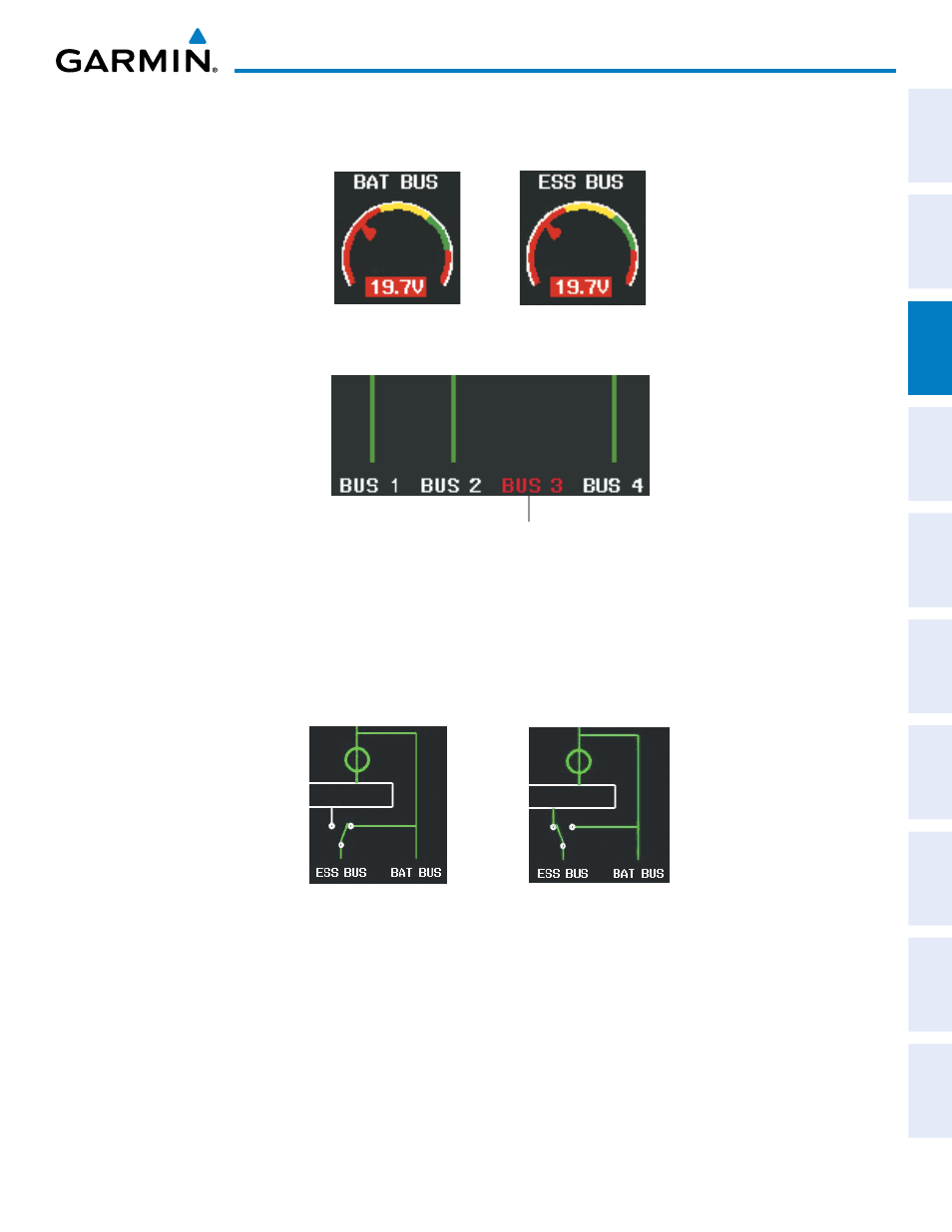
Battery and essential bus voltages are displayed using gauges. DC buses are shown in green when energized.
When not energized, the connection line to the main bus is removed and the bus label is displayed in red.
Figure 3-20 Battery and Essential Bus Low Voltage
Figure 3-21 DC Bus Status
Bus Not Energized
The Emergency Buses switch has two positions, UP (open) and DN (ground). If the switch is in the UP
position, the essential bus is connected to the battery bus. If the switch is in the DN position, the essential bus
is connected to the main bus.
Figure 3-22 Essential Bus Connections
Essential Bus Connected
to the Battery Bus
Essential Bus Connected
to the Main Bus
A red “X” over a component indicates invalid data or a failed unit.