Rdr_to_pc_parameters, Contactless smart card protocol, Atr generation – ACS ACR1283L User Manual
Page 17: Atr format for iso 14443 part 3 piccs
ACR1283L – Reference Manual
Version 1.00
www.acs.com.hk
Page 17 of 55
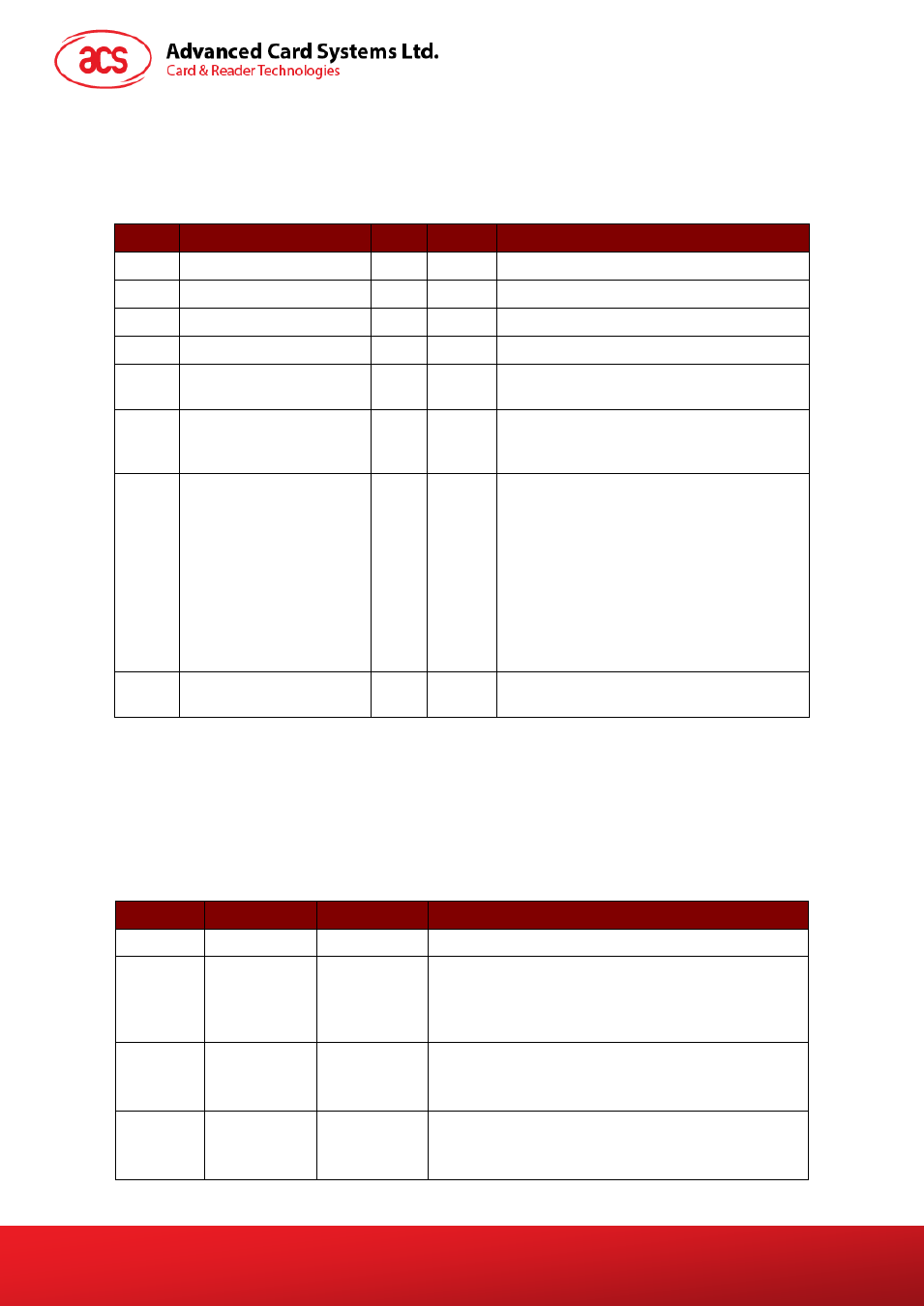
5.2.2.4. RDR_to_PC_Parameters
This message is sent by ACR1283L in response to PC_to_RDR_GetParameters,
PC_to_RDR_ResetParameters and PC_to_RDR_SetParameters messages.
Offset
Field
Size
Value
Description
0
bMessageType
1
82h
1
dwLength
4
Size of extra bytes of this message.
5
bSlot
1
Same value as in Bulk-OUT message.
6
bSeq
1
Same value as in Bulk-OUT message.
7
bStatus
1
Slot status register as defined in CCID
section 4.2.1.
8
bError
1
Slot error register as defined in CCID
section 4.2.1 and this specification section
5.2.8.
9
bProtocolNum
1
Specifies what protocol data structure
follows.
00h = Structure for protocol T=0
01h = Structure for protocol T=1
The following values are reserved for
future use:
80h = Structure for 2-wire protocol
81h = Structure for 3-wire protocol
82h = Structure for I2C protocol
10
abProtocolDataStructure Byte
array
Protocol Data Structure as summarized in
section 5.2.3.
5.3. Contactless Smart Card Protocol
5.3.1.
ATR Generation
If the reader detects a PICC, an ATR is sent to the PCSC driver for identifying the PICC.
5.3.1.1. ATR Format for ISO 14443 Part 3 PICCs
Byte
Value (Hex) Designation
Description
0
3B
Initial Header
1
8N
T0
Higher nibble 8 means: no TA1, TB1, TC1 only TD1
is following.
Lower nibble N is the number of historical bytes
(HistByte 0 to HistByte N-1)
2
80
TD1
Higher nibble 8 means: no TA2, TB2, TC2 only TD2
is following.
Lower nibble 0 means T = 0
3
01
TD2
Higher nibble 0 means no TA3, TB3, TC3, TD3
following.
Lower nibble 1 means T = 1