ACS ACR1283L User Manual
Page 14
ACR1283L – Reference Manual
Version 1.00
www.acs.com.hk
Page 14 of 55
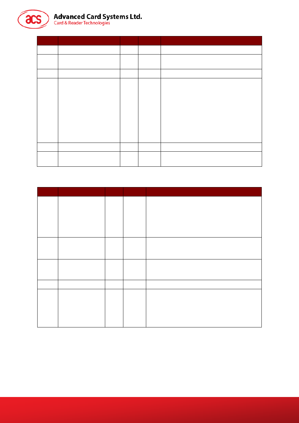
Offset
Field
Size
Value
Description
1
dwLength
4
Size of extra bytes of this message.
5
bSlot
1
Identifies the slot number for this
command.
6
bSeq
1
Sequence number for command.
7
bProtocolNum
1
Specifies what protocol data structure
follows.
00h = Structure for protocol T=0
01h = Structure for protocol T=1
The following values are reserved for
future use:
80h = Structure for 2-wire protocol
81h = Structure for 3-wire protocol
82h = Structure for I2C protocol
8
abRFU
2
Reserved for future use.
10
abProtocolDataStructure Byte
array
Protocol Data Structure.
Protocol Data Structure for Protocol T=0 (dwLength=00000005h)
Offset
Field
Size
Value
Description
10
bmFindexDindex
1
B7-4 – FI – Index into the table 7 in ISO/IEC
7816-3:1997 selecting a clock rate conversion
factor
B3-0 – DI - Index into the table 8 in
ISO/IEC 7816-3:1997 selecting a baud rate
conversion factor
11
bmTCCKST0
1
B0 – 0b, B7-2 – 000000b
B1 – Convention used (b1=0 for direct, b1=1 for
inverse)
Note: The CCID ignores this bit.
12
bGuardTimeT0
1
Extra Guardtime between two characters. Add 0
to 254 etu to the normal guardtime of 12etu. FFh
is the same as 00h.
13
bWaitingIntegerT0
1
WI for T=0 used to define WWT
14
bClockStop
1
ICC Clock Stop Support.
00h = Stopping the Clock is not allowed
01h = Stop with Clock signal Low
02h = Stop with Clock signal High
03h = Stop with Clock either High or Low