Using the 31bandgeq – Yamaha M7CL-32 User Manual
Page 177
Graphic EQ operations
M7CL Owner’s Manual
Gr
aphic EQ and eff
ects
16
177
You will use the Centralogic section’s faders 1–8 and
[ON] keys to control the 31BandGEQ.
1
Refer to steps 1–6 in the “Virtual rack oper-
ations” (
→ p. 172) to mount a 31BandGEQ
in a rack and set its input source and output
destination.
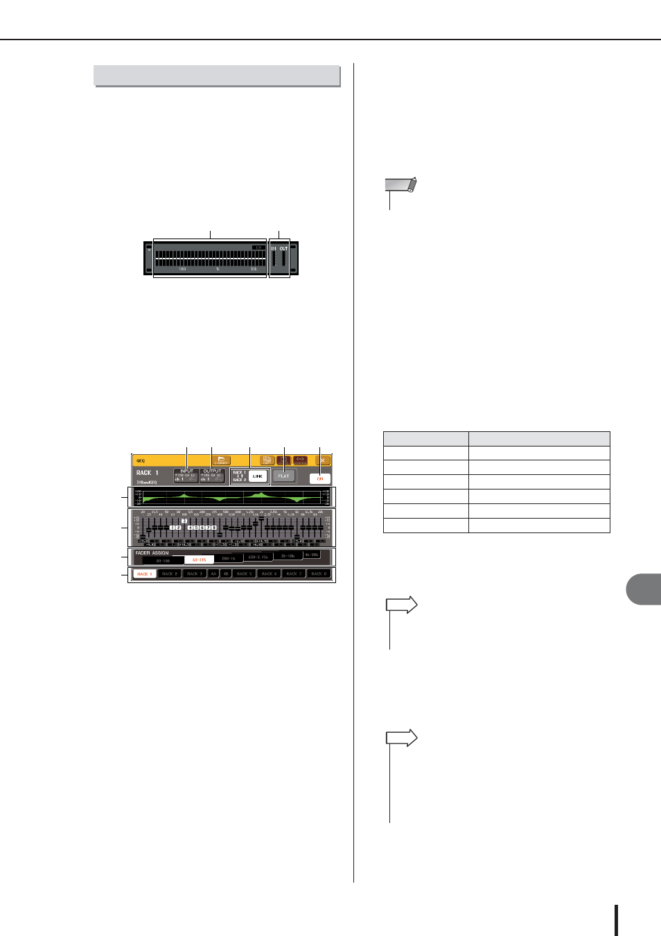
The rack in which the 31BandGEQ is mounted will
show the approximate settings and input/output levels.
1 Rack graphic display area
B Input/output meters
This indicates the level of the signals before and after
the 31BandGEQ.
2
In the GEQ/EFFECT field, press the rack in
which you mounted the 31BandGEQ.
The GEQ popup window will appear. In the GEQ
popup window you can use the tabs to switch between
the eight racks.
1 EQ graph
This indicates the approximate response of the current
31BandGEQ settings.
B Faders
These faders indicate the amount of boost/cut for each
band of the 31BandGEQ. The actual values are shown
in the numerical boxes below.
C FADER ASSIGN field
In this field you can select the group of bands that will
be controlled by the Centralogic section’s faders.
D Rack select tabs
These tabs switch between racks 1–8. For a rack in
which a Flex15GEQ is mounted, the tabs will be split
as xA and xB (x is the rack number).
E INPUT button
This button displays the OUTPUT CH SELECT
popup window, where you can select the input source
of the rack.
F OUTPUT button
This button displays the INPUT CH SELECT popup
window, where you can select the output destination of
the rack.
G GEQ LINK button
This button links adjacent GEQ units. In the case of a
31BandGEQ, the GEQ units in adjacent odd-num-
bered/even-numbered racks will be linked.
H FLAT button
This returns all bands of the currently selected GEQ to
0 dB.
I GEQ ON/OFF button
Switches the currently selected GEQ on/off.
3
Press the GEQ ON/OFF button to turn on
the 31BandGEQ.
4
Press one of the buttons in the FADER
ASSIGN field to select the group of bands
you will control using the Centralogic sec-
tion’s faders.
The buttons of the FADER ASSIGN field correspond
to the following groups of bands.
When you press one of these buttons, the faders for the
bands selected on the screen will turn white, and the
numbers of the corresponding faders in the Central-
ogic section will be displayed.
5
Operate the faders of the Centralogic sec-
tion.
The corresponding frequency region will be boosted
or cut.
Using the 31BandGEQ
2
1
5
6
7
8
9
4
3
2
1
Button name
Bands
20-100 button
The eight bands 20.0 Hz–100 Hz
63-315 button
The eight bands 63.0 Hz–315 Hz
200-1k button
The eight bands 200 Hz–1.00 kHz
630-3.15k button
The eight bands 630 Hz–3.15 kHz
2k-10k button
The eight bands 2.00 kHz–10.0 kHz
4k-20k button
The eight bands 4.00 kHz–20.0 kHz
• The GEQ LINK button is shown only if linking is possible.
NOTE
• The above operation is possible even if the Centralogic sec-
tion is locked. When you turn off the button in the FADER
ASSIGN field, it will return to the locked state.
HINT
• When a fader of the Centralogic section is in the center (flat)
position, the corresponding [ON] key will go dark. This indi-
cates that the corresponding band is not being modified. If
you raise or lower the fader even lightly, the [ON] key will light,
indicating that this band is being modified. If you press a lit
[ON] key to make it go dark, the corresponding band will
immediately return to the flat state.
HINT