2 cable pin assignments – ZyXEL Communications ES-3148 Series User Manual
Page 291
Chapter 38 Product Specifications
ES-3148 User’s Guide
291
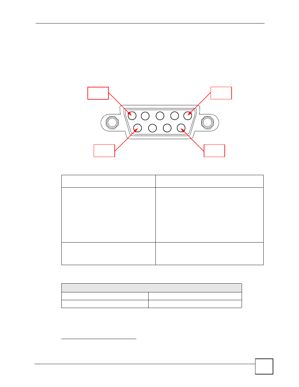
38.2 Cable Pin Assignments
In a serial communications connection, generally a computer is DTE (Data Terminal
Equipment) and a modem is DCE (Data Circuit-terminating Equipment). The Switch is DCE
when you connect a computer to the console port. The Switch is DTE when you connect a
modem to the dial backup port.
3
Figure 164 Console/Dial Backup Port Pin Layout
3.
Pins 2,3 and 5 are used.
Table 122 Console/Dial Backup Port Pin Assignments
CONSOLE Port RS – 232 (Female) DB-9F
DIAL BACKUP RS – 232 (Male) DB-9M (Not on all
models)
Pin 1 = NON
Pin 2 = DCE-TXD
Pin 3 = DCE –RXD
Pin 4 = DCE –DSR
Pin 5 = GND
Pin 6 = DCE –DTR
Pin 7 = DCE –CTS
Pin 8 = DCE –RTS
PIN 9 = NON
Pin 1 = NON
Pin 2 = DTE-RXD
Pin 3 = DTE-TXD
Pin 4 = DTE-DTR
Pin 5 = GND
Pin 6 = DTE-DSR
Pin 7 = DTE-RTS
Pin 8 = DTE-CTS
PIN 9 = NON.
The CON/AUX port also has these pin
assignments. The CON/AUX switch changes
the setting in the firmware only and does not
change the CON/AUX port’s pin assignments.
Switchs with a CON/AUX port also have a 9-pin
adaptor for the console cable with these pin
assignments on the male end.
Table 123 Ethernet Cable Pin Assignments
WAN / LAN ETHERNET CABLE PIN LAYOUT
Straight-through
Crossover
(Switch)
(Adapter) (Switch)
(Switch)
Pin 1
Pin 5
Pin 6
Pin 9