Wolf Induction s ICBCT30I User Manual
Page 11
11
I N S TA L L AT I O N
I N S T R U C T I O N S
M U LT I P L E C O O K TO P
I N S TA L L AT I O N
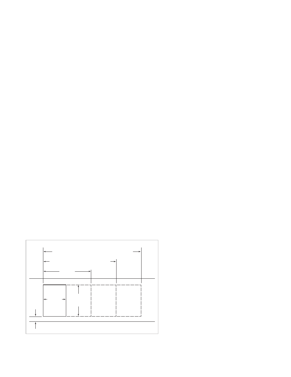
If the framed induction cooktop is to be used
with any combination of additional cooktop
units or modules with a filler strip, the cut-out
width is calculated by adding the correspon-
ding units’ cut-out dimensions plus 32 mm for
each additional unit. Refer to the illustration
below.
IMPORTANT NOTE: For Model ICBCT15I/S,
the cut-out width should be increased from
340 mm to 356 mm when installed with
multiple units.
IMPORTANT NOTE: Unframed induction
cooktops are not designed to be installed in
combination with other cooktops.
IMPORTANT NOTE: When multiple units are
installed side by side, each unit must have its
own separate recommended electrical circuit.
64 mm
min
FRONT OF COUNTERTOP
489 mm
CUT-OUT
DEPTH
743 mm
TWO MODULES WIDTH
1130 mm –
THREE MODULES WIDTH OR
1124 mm –
762 mm COOKTOP AND ONE MODULE
1518 mm
– FOUR MODULES WIDTH OR
1511 mm
– 762 mm COOKTOP AND TWO MODULES OR
1276 mm
– 914 mm COOKTOP AND ONE MODULE
356 mm
CUT-OUT
WIDTH
Countertop cut-out dimensions for installation of multiple cooktops
A C C E S S O R I E S
Optional acces-
sories are available
through your
Wolf dealer. To
obtain local dealer
information, visit
our website,
wolfappliance.com.
When two or more modules are installed
together, an integrated module filler strip
(IFILLER/S) is recommended. If a 762 mm
downdraft ventilation system is also installed,
an integrated module support for downdraft
ventilation (ISUPPORT) is also required.
Contact your Wolf dealer for information on
these accessory components.